Sensorless Field-Oriented Control of PMSM Using STM32 Processor Based Boards
This example implements the field-oriented control (FOC) technique to control the speed of a three-phase permanent magnet synchronous motor (PMSM). For details about FOC, see Field-Oriented Control (Motor Control Blockset).
This example uses the sensorless position estimation technique. You can select either the sliding mode observer or flux observer to estimate the position feedback for the FOC algorithm used in the example.
A closed-loop FOC algorithm is used to regulate the speed and torque of a three-phase PMSM. This example uses STM32 peripheral blocks from the STM32™ Microcontroller Blockset and MCB library blocks from Motor Control Blockset™. Run slLibraryBrowser in MATLAB® Command window to open the Simulink Library Browser. In the opened Simulink Library Browser, you can find STM32 Processor Based Boards driver library under STM32 Microcontroller Blockset.
The Sliding Mode Observer (SMO) block generates a sliding motion on the error between the measured and estimated position. The block produces an estimated value that is closely proportional to the measured position. The block uses stator voltages  and currents
  as inputs and estimates the electromotive force (emf) of the motor model. It uses the emf to further estimate the rotor position and rotor speed. The Flux Observer block uses identical inputs
  to estimate the stator flux, generated torque, and the rotor position.
Prerequisites
Complete the following tutorials:
NOTE: Complete all the hardware connections and obtain the ADC offset values of by completing Open-Loop Control of 3-Phase AC Motors Using STM32 Processor Based Boards.
Required Hardware
Available Models
You can use the mcb_pmsm_foc_sensorless_nucleo_f401re or mcb_pmsm_foc_sensorless_nucleo_g474re model with the X-NUCLEO-IHM07M1 expansion board for both simulation and code generation. You can also use the open_system command to open the Simulink® models. For example, use this command for a STM32 Processor based Boards:
open_system('mcb_pmsm_foc_sensorless_nucleo_f401re.slx');
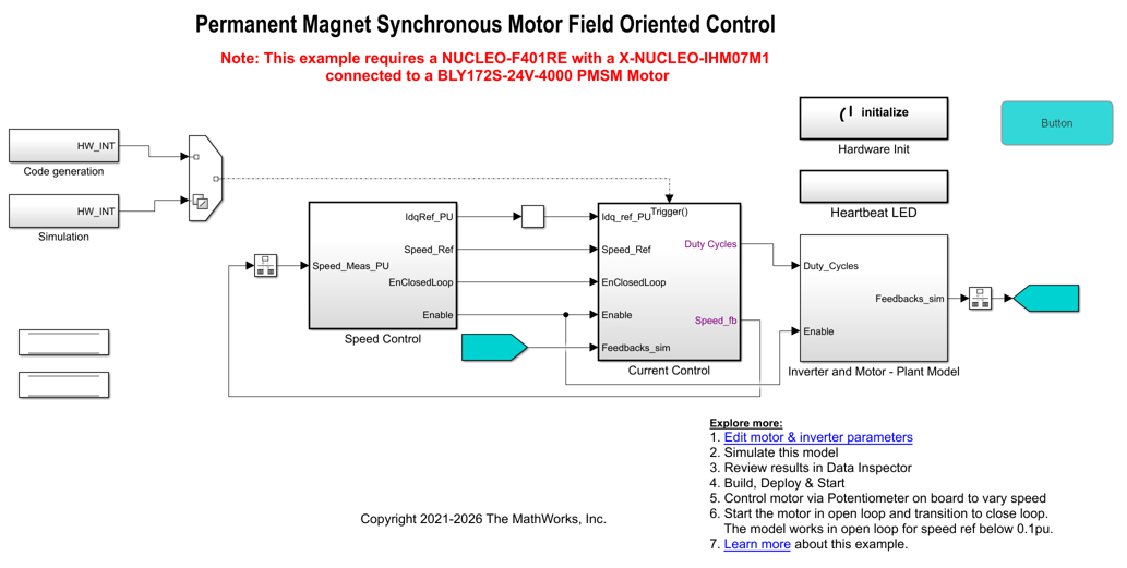
Click Edit motor & inverter parameters in the model to change the model parameters to fit your specific motor. Match motor voltage and power characteristics to the controller. In this example the current motor parameters is configured for BLY172S-24V-4000 Brushless DC motor.
A conventional voltage-source inverter drives motor. The controller algorithm generates three pulse width modulation (PWM) signals using a vector PWM technique for six power switching devices. The inverter measures the current of the two motor inputs (ia and ib) using two channels in injected group of analog to digital converter (ADCs) and sends the measurements to the torque control algorithm.
Peripheral Configurations
STM32CubeMX Configurations
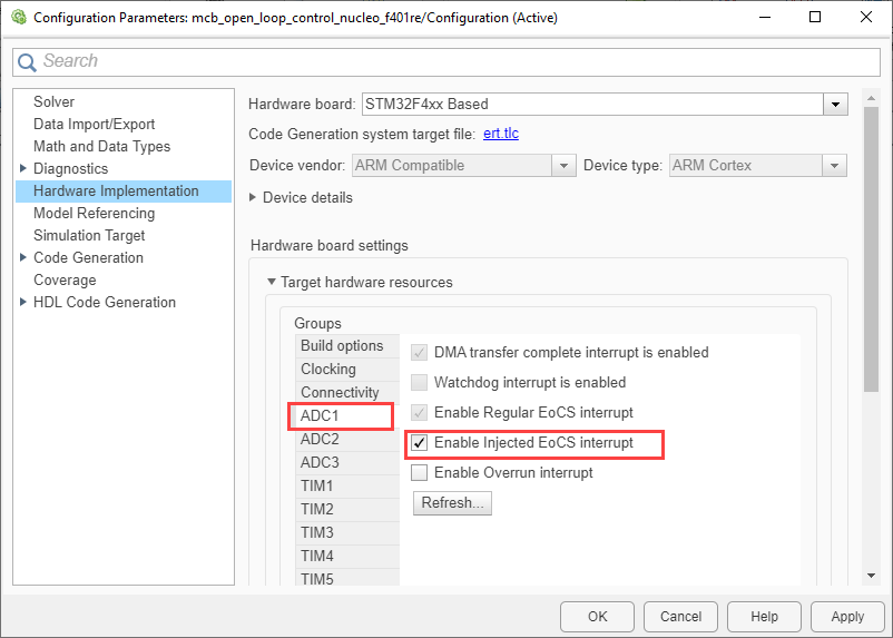
ADC configuration
The ADC and PWM synchronization occurs such that ADC injected group conversions start based on Timer 1 update events.
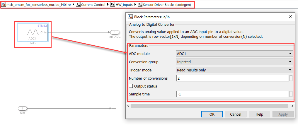
The ADC channel is configured to read current feedback from the injected group conversions of ADC 1 and the reference speed from regular group conversions.

PWM Configuration
PWM frequency and PWM channels are configured. The
Timer1is configured to generate update events to synchronize the ADC with the PWM. This synchronization is important to read current feedback at right time.The repetition counter is set to 1 to ensure update events occur once every period.

Peripheral Block Configurations
Double-click the blocks to open the block parameter configurations. Ensure the specified parameter values are the same if you want to run this example on a different hardware board.
Configure Analog to Digital Converter block
The algorithm in this example uses asynchronous scheduling. The pulse width modulation (PWM) block triggers the ADC conversion. At the end of the conversion, the ADC posts an interrupt that triggers the open-loop algorithm.
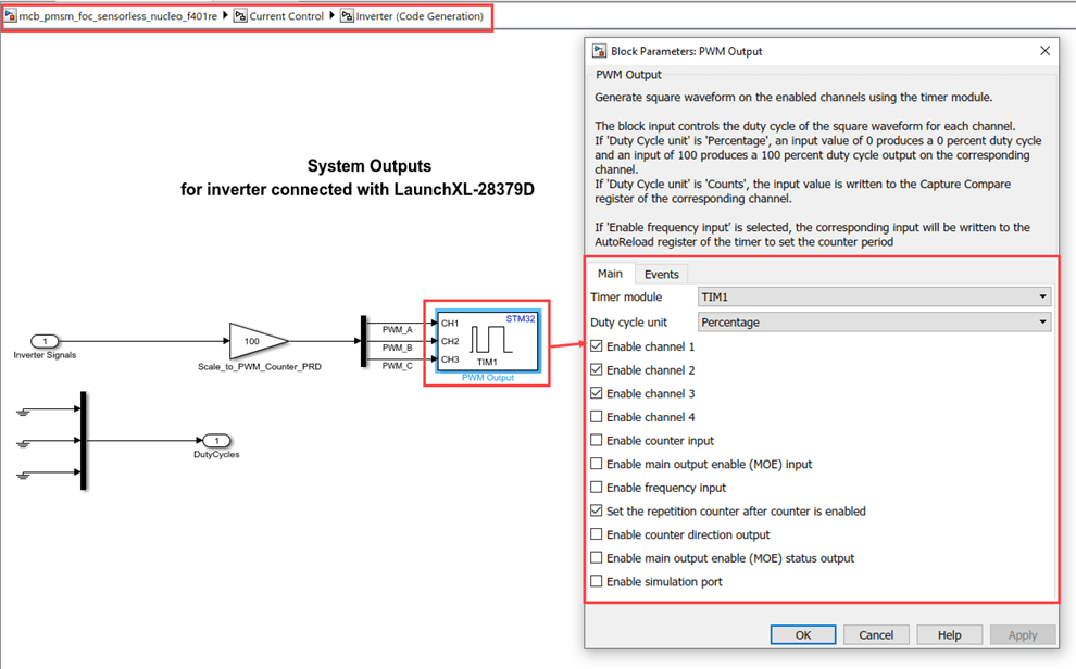
Configure PWM Output block
Select the Set the repetition counter after counter is enabled parameter to update the event when the timer counter overflows.
Simulate Model
This example supports simulation. Follow these steps to simulate the model.
1. Open a model included with this example.
2. Click Run on the Simulation tab to simulate the model.
3. Click Data Inspector on the Simulation tab to view and analyze the simulation results.
Generate Code, Deploy and Run on Target Hardware
This section shows you to generate code and run the motor. Before proceeding, Open the script "stm32_pmsm_foc_data.m" or "stm32_nucleo_g474_pmsm_foc_data" based on target hardware used and enter the correct parameters of motor, inverter power supply, and control system related variables. The default values used in the script is tested on BLY172S motor with IHM07M1 inverter board.
1. Simulate the target model and observe the simulation results.
2. Complete the hardware connections. For more, see Open-Loop Control of 3-Phase AC Motors Using STM32 Processor Based Boards
3. Compute the ADC offset values obtained from the Open-Loop Control of 3-Phase AC Motors Using STM32 Processor Based Boards. For instructions, see Open-Loop Control of 3-Phase AC Motors Using STM32 Processor Based Boards.
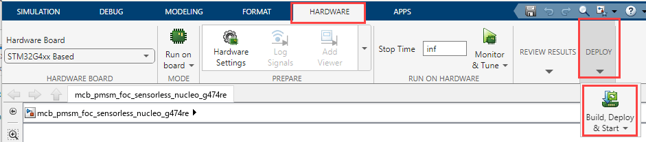
4. In the Hardware tab, click Build,Deploy & Start.
5. To spin the motor, press the (blue push button) on the IHM07M1 inverter board.
NOTE:
Before starting the motor, ensure to keep the potentiometer at 0 position by rotating the potentiometer in the anti-clockwise direction.
Press the Push button to start the motor. Now gradually rotate the potentiometer in the clockwise direction to increase the speed. The close loop will start after the reference speed crosses (
Speed_openLoop_PU * pmsm.N_base), (wherepmsm.N_baseandSpeed_openLoop_PUcan be set via the .M file "stm32_pmsm_foc_data" andpmsm.N_baseis the MATLAB™ workspace variable for base speed of the motor).The motor starts running in an open-loop when the reference speed is between 0 to
Speed_openLoop_PUxpmsm.N_base.
6. Click the Push button again, to start running the motor in the open-loop condition.
NOTE: Do not run the motor (using this example) in the open-loop condition for a long time duration. The motor may draw high currents and produce excessive heat.
7. Increase the motor reference speed beyond Speed_openLoop_PU value to switch from open-loop to closed loop.
NOTE: In this example, the motor is configured to run in only one direction.
8. To observe the debug signals use fast serial data monitoring two model approach. For more information, see Fast Serial Data Monitoring on STM32 Boards Using a Two-Model Approach.
Other Things to Try
You can try running the example using an SoC Blockset™ and analyze the results.
Try running the example using mcb_pmsm_foc_sensorless_nucleo_g474re model on
STM32G4xx Basedhardware board.You can also use Flux Observer algorithm instead of sliding mode observer(SMO).
More About
Open-Loop Control of 3-Phase AC Motors Using STM32 Processor Based Boards
Get Started with STMicroelectronics STM32 Processor Based Boards
Read Analog Voltages from External Sensors on an STM32 Processor
Signal Monitoring and Parameter Tuning of Generated PWM Output
Monitoring and Tuning Using STMicroelectronics STM32 Processor Based Boards
Fast Serial Data Monitoring on STM32 Boards Using a Two-Model Approach