Read Temperature from TMP102 Sensor Using Raspberry Pi
This example illustrates how to use Simulink® Support Package for Raspberry Pi® Hardware to configure and read temperature from a TMP102 sensor.
Introduction
Simulink Support Package for Raspberry Pi Hardware enables you to use the I2C interface to communicate with I2C devices. In this example, you will learn how to read temperature from TMP102 digital sensor. This sensor is connected to the Raspberry Pi board using the I2C bus. By default, TMP102 sensor outputs temperature values with 12-bit precision which corresponds to a resolution of 0.0625 degree Celsius. You can configure TMP102 to provide 13-bit temperature measurements when needed. For more details about the device, refer to the TMP102 datasheet.
This example shows how to program the Raspberry Pi board to read the temperature from the sensor using the I2C bus. It also illustrates how to program the Raspberry Pi board to initialize the sensor with some advanced settings.
Prerequisites
We recommend completing the Get Started with Simulink Support Package for Raspberry Pi Hardware example and completing the Communicate with Raspberry Pi Hardware example to learn about External mode. Refer to Raspberry Pi I2C Interface to know more about the I2C interface on Raspberry Pi.
Required Hardware
To run this example, you need the following hardware:
Raspberry Pi board
USB cable
Breadboard wires
A breadboard (recommended)
Task 1 - Connect TMP102 Sensor to Raspberry Pi Hardware
In this task, you have to connect the TMP102 sensor to the Raspberry Pi board. Refer to the following pin-out diagram of Raspberry Pi 3 Model B for connections.
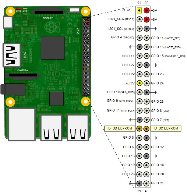
Attach the TMP102 sensor to the Raspberry Pi board using the following connections:
    TMP102 pin |   Raspberry Pi pin
 _ _ _ _ _ _ _ _ _ _ _ _ _ _ _ _ _ _ _ _ _
      VCC      |  3.3 V
      GND      |  GND
      SDA      |  I2C1_SDA (GPIO 2)
      SCL      |  I2C1_SCL (GPIO 3)
      ALT      |  Not Connected
      ADD0     |  GND
 _ _ _ _ _ _ _ _ _ _ _ _ _ _ _ _ _ _ _ _ _
This example shows Raspberry Pi 3 Model B connected to TMP102. However, you can connect any Raspberry Pi board supported by Simulink Support Package for Raspberry Pi Hardware. Use showPins to check the pin-out diagram of your Raspberry Pi board.
Task 2 - Configure Simulink Model for Raspberry Pi Hardware
In this task, you have to configure the model for the Raspberry Pi hardware.
1. Open the raspberrypi_I2C_temp Simulink model.

2. In your Simulink model, click Simulation > Model Configuration Parameters to open Configuration Parameters dialog.
3. Select the Hardware Implementation pane and select Raspberry Pi from the Hardware board parameter list. Do not change any other settings.
4. Click OK.
Task 3 - Configure Simulink Model to Read Temperature Using I2C Controller Read Block
In this task, you have to configure the model to read data from the TMP102 sensor using the I2C Controller Read block.
1. Open the raspberrypi_I2C_temp Simulink model.
2. Configure the I2C Controller Read block:
Open the I2C Controller Read block. Notice that the Peripheral address parameter of the block is set to '0x48'. The ADD0 pin of the TMP102 sensor is grounded which corresponds to a 7-bit address of 1001000 (0x48 in hexadecimal) according to the TMP102 datasheet.
The TMP102 sensor contains multiple registers. On power-up reading data from the device returns the value stored in register 0 - Temperature Register (Read Only). Leave the Enable register access parameter unchecked as you will read the Temperature Register in this step.
The Temperature Register has a size of 16-bit. It stores the 12-bit temperature value in a left justified 2's complement format. The TMP102 sensor sends data in Big Endian byte order. Select the Peripheral byte order to 'Big Endian', Data size (N) to 1, Data type to 'int16' (to take care of positive and negative temperature), and Sample Time to 0.1.
3. Notice the following in the model:
The Gain block is used to right shift the int16 data by 4 bits (division by 16) to right justify the upper 12 bits of the temperature measurement. The Gain block also multiplies the 12-bit data with the sensor resolution of 0.0625 to get the corresponding temperature in Celsius.
The two Constant blocks with values of 1 and 0 are used with a Switch block to compare the temperature reading against a threshold of 27 degree Celsius. When temperature value read from TMP102 exceeds the threshold Raspberry Pi user LED glows. Try pressing on the TMP102 chip to increase sensor temperature to observe this behavior.
Task 4 - Run Simulink Model in External Model (Monitor and Tune)
In this task, you will run the Simulink model in external mode to monitor the temperature. The Raspberry Pi user LED, marked ACT on the board, will indicate when the TMP102 reading exceeds a specified temperature threshold.
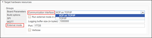
1. Go to Modeling tab and press Ctrl+E to open the Configuration Parameters dialog box.
2. Browse to Hardware Implementation > Target hardware resources > External Mode, and set the Communication Interface parameter to XCP on TCP/IP.
3. In the model, identify the signals to be logged for monitoring during simulation. Select the identified signal, open its context menu, and click the icon corresponding to Enable Data Logging. Simulink displays a logged signal indicator for each logged signal. For more information, see Mark Signals for Logging.
In this example, the output of the Gain and the Data Type Conversion blocks are marked for logging.
4. On the Hardware tab of the Simulink model, in the Mode section, select Run on board and then click Monitor & Tune.
When new simulation data becomes available in Simulation Data Inspector(SDI), the Simulation Data Inspector button appears highlighted. The Display block in the model shows the TMP102 sensor temperature reading in degree Celsius. The color of the Lamp block changes to green when the Display block in the model shows a temperature above 27 degree Celsius. The Raspberry Pi onboard ACT LED also glows when the temperature is above 27 degree Celsius.
5. Change the threshold value in the Switch block according to your ambient temperature and click Apply. See the onboard ACT LED glow when the temperature exceeds the new threshold value.
7. Click the Simulation Data Inspector button to inspect and compare data from multiple simulations for validating model designs. For more information on SDI, see Analyze Simulation Results.
8. Click Stop to end the Monitor and Tune execution.
Task 5 - Configure Simulink Model to Initialize Temperature Sensor to 13-bit Extended Mode
This task shows you how to write to one of the registers on the TMP102 sensor to configure it to 13-bit Extended mode.
1. Open the raspberrypi_I2C_temp_init Simulink model.
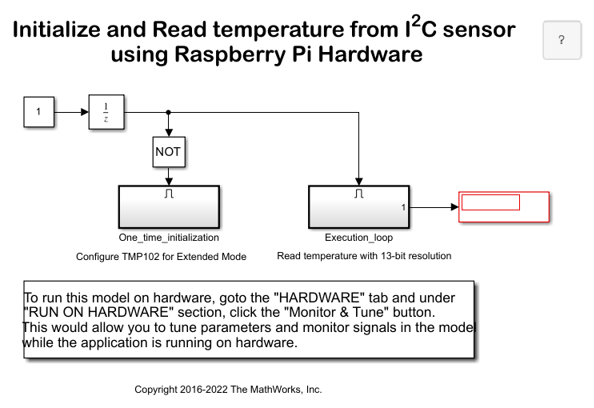
2. Notice the two subsystems in the model:
The One_time_initialization subsystem configures the TMP102 sensor to run in 13-bit Extended mode.
The Execution_loop subsystem reads the 13-bit temperature value.
The One_time_initialization subsystem executes only once at model initialization while the Execution_loop subsystem runs at every sample time hit. This selective execution of subsystems is handled using the Unit Delay and the Enabled Subsystem blocks from the Simulink library.
The sensor is configured in Extended mode by setting the EM bit in the Configuration Register to 1 as per the TMP102 datasheet. This means a value of '0x60B0' to be written to the Configuration Register located at address 1 of the TMP102 sensor.
3. Open the One_time_initialization subsystem.
4. Configure the I2C Controller Write block to write to the Configuration Register of the TMP102 sensor:
Open the I2C Controller Write block. The Peripheral address parameter of the block is set to '0x48'.
Select the Enable register access parameter. Then the Peripheral register address parameter appears in the block.
Set the Peripheral register address parameter to 1. The address of the Configuration Register is 1 as per TMP102 datasheet.
Set the Peripheral byte order parameter to Big Endian as data needs to be sent over the I2C bus in Big Endian byte order.
5. Notice the following in the One_time_initialization subsystem:
The Constant block holds a value of '0x60B0' of uint16 data type to be written to the Configuration Register.
The I2C Controller Read block connected to the Display block ensures that the correct data is written to the Configuration Register. The I2C Controller Read block uses the same settings as the I2C Controller Write block. The Data size (N) parameter is set to 1 and Data type is set to uint16.
The priority of the I2C Controller Write block is set to 1. The priority of the I2C Controller Read block is set to any value higher than 1 to ensure you read the value of the Configuration Register after it is set. To set the Priority of a block, right-click the block > Properties > General > Priority. To know more about block priorities and their impact on block execution order, refer to Specify Block Properties.
6. Open the Execution_loop subsystem and observe the following:
This subsystem resembles the
raspberrypi_I2C_tempmodel.
The Gain block performs a division by 8 that corresponds to a right shift of 3 bits. The division right justifies the 13-bit temperature value.
Task 6 - Run Simulink Model in External Mode (Monitor and Tune)
In this task, you will run the Simulink model in external mode to monitor the temperature.
1. On the Hardware tab of the Simulink model, in the Mode section, select Run on board and then click Monitor & Tune.
2. Open the One_time_initialization subsystem.
3. Verify that the Display block shows a value of '0x60B0' in hexadecimal corresponding to the desired Configuration Register value.
4. Monitor the Display block connected to the Execution_loop subsystem to observe the TMP102 temperature reading in degree Celsius. The Raspberry Pi onboard ACT LED glows when the Display block in the model shows a temperature above 27 degree Celsius.
5. Change the threshold value in the Switch block according to your ambient temperature and click Apply. See the onboard ACT LED glow when the temperature exceeds the new threshold value.
6. (Optional) You can click the Simulation Data Inspector button to inspect and compare data from multiple simulations for validating model designs.
7. Click Stop to end the Monitor and Tune execution.
Task 7 - Log Temperature Value into MAT File
With the Simulink Support Package for Raspberry Pi hardware, you can log signals present in your Simulink model. In this task, we will log the temperature value read from the I2C sensor.
1. Attach a To Workspace block to the output of the Execution_loop subsystem.
2. Double-click the To Workspace block to configure it.
3. Follow the steps mentioned in Task-2 of Log Signals in MAT File Format Using Raspberry Pi to enable MAT file logging.
4. In your Simulink model, set the time for which you wish to log the signal.
5. You can either simulate the model or run the model in external mode (Monitor and Tune).
6. After the specified time has elapsed, you can import the MAT files into MATLAB for further analysis. Follow the steps mentioned in Task-4 of Log Signals in MAT File Format Using Raspberry Pi to import the MAT files generated on your Raspberry Pi hardware.
Other Things to Try
Configure the TMP102 sensor to restore the output to 12-bit.
Change the conversion rate of the ADC in the sensor using the Configuration Register. Refer to the Continuous-Conversion Mode and the Configuration Register sections in TMP102 datasheet for more details.
Refer to the TMP102 datasheet and try to configure TMP102 to run in Shutdown Mode and/or Comparator Mode. Try to change the values of High-and-Low-Limit-Registers.
Follow the steps in this example to communicate with other I2C sensors such as SenseHAT.
Select a Web Site
Choose a web site to get translated content where available and see local events and offers. Based on your location, we recommend that you select: United States.
You can also select a web site from the following list
Americas
- América Latina (Español)
- Canada (English)
- United States (English)
Europe
- Belgium (English)
- Denmark (English)
- Deutschland (Deutsch)
- España (Español)
- Finland (English)
- France (Français)
- Ireland (English)
- Italia (Italiano)
- Luxembourg (English)
- Netherlands (English)
- Norway (English)
- Österreich (Deutsch)
- Portugal (English)
- Sweden (English)
- Switzerland
- United Kingdom (English)