Compare Profile Differences Using System Composer Comparison Tool
This example shows how to use the System Composer Comparison Tool to compare two System Composer™ profiles. You can compare profiles to generate a comparison report that includes added, modified, or deleted profiles, stereotypes, and properties.
In this example, the model represents a mobile robot hardware architecture. For more information about profiles, see Extend System Composer Language Elements Using Profiles.
Open System Composer Comparison Tool
To compare profiles, create comparison reports for the XML files that contain the profiles. In this example, you can compare the original version of the MobileRobotProfile profile with the MobileRobotProfileEdited profile.
To open the System Composer Comparison Tool, enter this command.
visdiff("MobileRobotProfile.xml","MobileRobotProfileEdited.xml");
Alternatively, from the Files panel, select the two profile files, right-click, and select Compare Selected Files/Folders.
Understand Profile Comparison Changes
Review the comparison report to explore the differences in your profiles. The comparison report highlights rows according to the type of difference:
Insertion
 — Added elements to the right side that did not exist on the left side
Deletion
 — Removed elements that did exist on the left side but not on the right side
Modification
 — Changes to existing elements that exist on both the left and right sides
Compare Profile Differences
The System Composer comparison report includes changes to profiles, stereotypes, and properties.
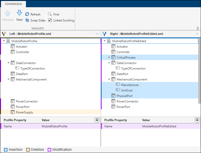
In this report, the tool selects the MobileRobotProfile node and shows the details in a pane on the bottom of the report. In the details pane, the modified name is colored in purple. You can see that the Name property of the profile was modified to be MobileRobotProfileEdited in the MobileRobotProfileEdited profile.
To step through the differences, on the Comparison tab, in the Navigate section, use the Next and Previous buttons. Alternatively, use the up and down arrows on your keyboard to navigate the report.
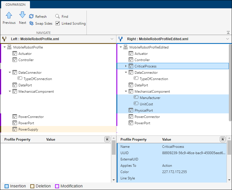
The tool selects the CriticalProcess node, which is colored in blue to represent the insertion of this element. You can see that the CriticalProcess stereotype with a SafetyFactor property is inserted in the MobileRobotProfileEdited profile.
Click Next until the tool selects the TypeOfConnection node, which is colored in purple to represent the modification of this element. In the details pane, you can see that the <Default> property is modified to be 'USB' in the MobileRobotProfileEdited profile.

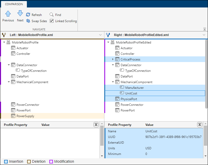
Click Next until the tool selects the UnitCost node, which is colored in blue to represent the insertion of this element. You can see that the UnitCost property is inserted in the MobileRobotProfileEdited profile, under the MechanicalComponent stereotype.
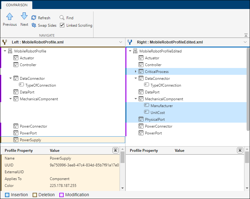
Click Next until the tool selects the PowerSupply node, which is colored in yellow to represent the deletion of this element. You can see that the Name, UUID, Applies To, and Color properties of the PowerSupply stereotype are deleted in the MobileRobotProfileEdited profile.