Main Content

Deinterlacing

Remove interlacing effect

  • Deinterlacing block

Libraries:
Computer Vision Toolbox / Analysis & Enhancement

Description

The Deinterlacing block removes the motion artifact known as the interlacing effect from an interlaced image or a video. An interlaced image or video frame comprises of top field and bottom field that has slightly different capture times. The odd numbered lines in an interlaced image constitute the top field and the even numbered lines constitute the bottom field.

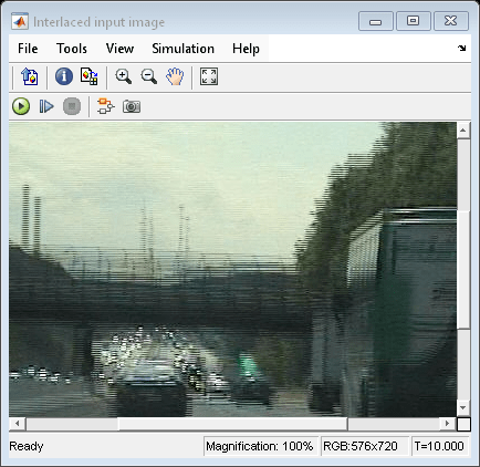
When you display an interlaced image, the temporal difference between the top and bottom fields causes a visible artifact where the alternate lines in the interlaced image appear displaced.

This artifact is known as the interlacing effect and can be corrected through deinterlacing techniques. You can use the Deinterlacing block to convert an interlaced video into a deinterlaced video by using one of these methods:

  • Line repetition

  • Linear interpolation

  • Vertical temporal median filtering

You can use this block to deinterlace both intensity and color images.

Ports

Input

expand all

Interlaced input, specified as a numeric matrix, 3-D numeric array, image, or video.

To input an interlaced image, read the image file by using the Image From File or Image From Workspace block. The image can also be a video frame. To input an interlaced video, read the video file by using the From Multimedia File or Video From Workspace block.

Data Types: single | double | int8 | int16 | int32 | int64 | uint8 | uint16 | uint32 | uint64 | fixed point

Output

expand all

Deinterlaced output, returned as a numeric matrix, 3-D numeric array, image, or video. The output is of same size and datatype as that of the input.

Data Types: single | double | int8 | int16 | int32 | int64 | uint8 | uint16 | uint32 | uint64 | fixed point

Parameters

expand all

Main Tab

Use this parameter to specify the method for deinterlacing the input data.

  • If you set the Method parameter value to Line repetition, the values in the bottom field of the interlaced image or video frame are replaced with the values in the preceding top field.

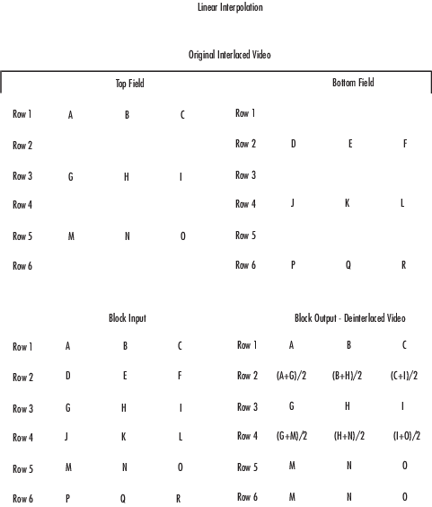
  • If you set the Method parameter value to Line interpolation, the values in a bottom field are computed as the average of the values in the two neighboring top fields.

  • If you set the Method parameter value to Vertical temporal median filtering, the values in a bottom field are computed as the median of the values in the bottom field and its two neighboring top fields.

You can use this parameter to specify if the interlaced input is stored in row major order. When you select this parameter, the block assumes that the input buffer contains contiguous data elements of an array that are arranged sequentially row by row. Otherwise, the blocks assumes that the buffer stores data in the column major order such that the elements are arranged sequentially column by column.

Use this parameter only when

  • You are developing algorithms to run on an embedded target that uses the row-major format.

  • You want to limit the additional processing required to take the transpose of signals at the interfaces of the row-major and column-major systems.

When you select this check box, the first two dimensions of the Deinterlacing block's input are swapped.

Data Types Tab

To enable options on the Data Types tab, set the Method parameter in the Main tab to Linear interpolation.

Fixed-point operational parameters

Specifies the rounding mode for the block to use when the specified data type and scaling cannot exactly represent the result of a fixed-point calculation.

See Rounding Modes for more information on the available options.

When you select this parameter, the block saturates the result of its fixed-point operation. When you clear this parameter, the block wraps the result of its fixed-point operation.

For details on saturate and wrap, see Overflow Handling for fixed-point operations.

Fixed-point data types

Use this parameter to specify the data type and scaling of the accumulator (sum).

  • When you select Binary point scaling, you can enter the word length and the fraction length of the accumulator, in bits. The default value for word length is set to 12 and fraction length is set to 3. The data type format is same as that of the input data format, signed or unsigned.

  • When you select Same as input, the word length and the fractional length of the accumulator match those of the input.

Use this parameter to specify the data type and scaling of the output data.

  • When you select Same as input, the word length and the fractional length of the accumulator match those of the input.

  • When you select Binary point scaling, you can enter the word length and the fraction length of the output, in bits. The default value for word length is set to 8 and fraction length is set to 0. The data type format is same as that of the input data type format, signed or unsigned.

Select this parameter to prevent the fixed-point tools from overriding the data types you specify on the block mask. For more information, see fxptdlg (Fixed-Point Designer), a reference page on the Fixed-Point Tool.

Block Characteristics

Data Types

double | fixed point | integer | single

Multidimensional Signals

yes

Variable-Size Signals

yes

Extended Capabilities

C/C++ Code Generation
Generate C and C++ code using Simulink® Coder™.

Version History

Introduced before R2006a