visionhdl.BirdsEyeView
Transform front-facing camera image into top-down view
Description
The visionhdl.BirdsEyeView
System object™ warps a front-facing camera image into a top-down view. It uses a
hardware-efficient architecture that supports HDL code generation. This object also requires
the Computer Vision Toolbox™ product.
You must provide the homography matrix that describes the transform. This matrix can be calculated from physical camera properties, or empirically derived by analyzing an image of a grid pattern taken by the camera. The object uses the matrix to compute the transformed coordinates of each pixel. The transform does not interpolate between pixel locations. Instead it rounds the result to the nearest coordinate.
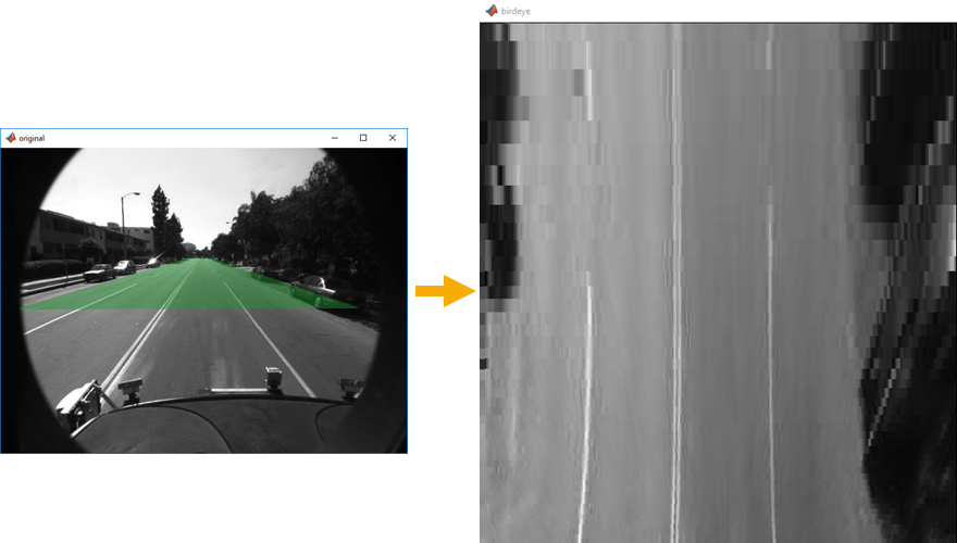
The object operates on a trapezoidal region of the input image below the vanishing point. These images show the input region selected for transformation and the resulting top-down view.
You can specify the number of lines in the transformed region and the size of the output frame. If the specified homography matrix cannot map from the requested number of lines to the requested output size, the object returns a warning.
Because the object replicates lines from the input region to create the larger output frame, it cannot complete the transform of one frame before the next frame arrives. The object ignores any new input frames while it is still transforming the previous frame. Therefore, depending on the stored lines and output size, the object can drop input frames. This timing also enables the object to maintain the blanking intervals of the input pixel stream.
To transform a front-facing camera image to top-down view:
Create the
visionhdl.BirdsEyeViewobject and set its properties.Call the object with arguments, as if it were a function.
To learn more about how System objects work, see What Are System Objects?
Creation
Description
birdsEyeXfrm = visionhdl.BirdsEyeView(
returns a bird's-eye transform System object, with the homography matrix set to hM,MaxBufferSize,PropertyName=Value)hM, and a buffer
size of MaxBufferSize pixels. You can optionally set additional
properties using name-value arguments.
Properties
Usage
Description
[
returns the bird's-eye view transformation of the input stream. The frame size of the
output stream corresponds to the size you configured in the
pixelout,ctrlout] = birdsEyeXfrm(pixelin,ctrlin)BirdsEyeViewPixels and BirdsEyeViewLines
properties.
This object uses a streaming pixel interface with a structure
for frame control signals. This interface enables the object to operate independently of image
size and format and to connect with other Vision HDL Toolbox™ objects. The object accepts and returns a scalar pixel value and control signals
as a structure containing five signals. The control signals indicate the validity of each pixel
and its location in the frame. To convert a pixel matrix into a pixel stream and control
signals, use the visionhdl.FrameToPixels object. For a
description of the interface, see Streaming Pixel Interface.
Input Arguments
Output Arguments
Object Functions
To use an object function, specify the
System object as the first input argument. For
example, to release system resources of a System object named obj, use
this syntax:
release(obj)
Algorithms
The transform from input pixel coordinate (x,y) to the bird's-eye pixel coordinate is derived from the homography matrix, h. The homography matrix is based on physical parameters and therefore is a constant for a particular camera installation.
The implementation of the bird's-eye transform in hardware does not directly perform this calculation. Instead, the object precomputes lookup tables for the horizontal and vertical aspects of the transform.
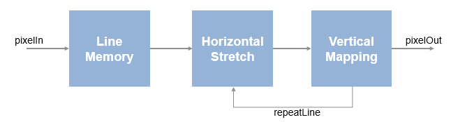
First, the object stores the input lines starting from the precomputed vanishing point.
The stored pixels form a trapezoid, with short lines near the vanishing point and wider lines
near the camera. This storage uses MaxBufferSize memory locations.
The horizontal lookup table contains interpolation parameters that describe the stretch of each line of the trapezoidal input region to the requested width of the output frame. Lines that fall closer to the vanishing point are stretched more than lines nearer to the camera.
The vertical lookup table contains the y-coordinate mapping, and how many times each line is repeated to fill the requested height of the output frame. Near the vanishing point, one input line maps to many output lines, while each line nearer the camera maps to a diminishing number of output lines.
The lookup tables use 3*MaxSourceLinesBuffered memory
locations.
Extended Capabilities
Version History
Introduced in R2017b
See Also
Blocks
Objects
Functions
imwarp(Image Processing Toolbox) |estimateGeometricTransform(Computer Vision Toolbox)
Topics
- Using the Single Camera Calibrator App (Computer Vision Toolbox)