DVB-S2X LDPC Decoder
R2026bDVB-S2X LDPC Decoder block
To add a block to a model, double-click the canvas and start typing the block name. Then, select the block from the list.
Libraries:
Wireless HDL Toolbox /
Error Detection and Correction
Description
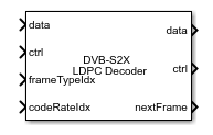
The DVB-S2X LDPC Decoder block implements a low-density parity-check (LDPC) decoder using layered belief propagation with min-sum approximation and normalized min-sum approximation algorithms for decoding LDPC codes according to the Digital Video Broadcasting Satellite Second Generation (DVB-S2X) standard. The block accepts log-likelihood ratio (LLR) values, a stream of control signals, a frame type, and a code rate as inputs and outputs decoded bits, a stream of control signals, and a signal that indicates when the block is ready to accept new inputs.
The DVB-S2X LDPC Decoder block supports early termination to help improve decoding performance and convergence speeds at high signal-to-noise-ratio (SNR) conditions. The block supports parallelism at two levels 45 and 180. The block supports scalar and vector values through the input/output (I/O) interface. It also supports forward error correction (FEC) frames of type normal, short, and medium with all the code rates supported by the DVB-S2X standard. For more information about the DVB-S2X standard, see [1].
The block provides an architecture suitable for HDL code generation and hardware deployment.
Examples
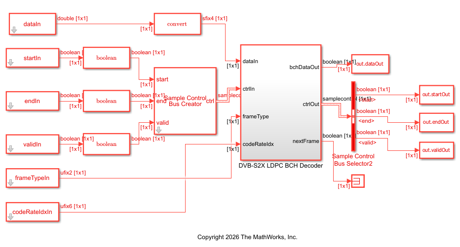
Decode and Recover Message Using DVB-S2X Standard FEC Decoder
Decode and recover message from codeword using FEC decoder according to DVB-S2X standard.
- Since R2026b
- Open Live Script
Ports
Input
LLR values, specified as a scalar or an eight-element column vector.
For HDL code generation, specify this value in signed fixed-point format. The input word length must be in the range from 4 to 16.
Data Types: int8 | int16 | signed fixed point
Control signals accompanying the sample stream, specified as a
samplecontrol bus. The bus includes the start,
end, and valid control signals, which indicate the
boundaries of the frame and the validity of the samples.
start— Indicates the start of the input frameend— Indicates the end of the input framevalid— Indicates that the data on the input data port is valid
For more details, see Sample Control Bus.
Data Types: bus
Type of FEC frame, specified as a Boolean scalar.
0— Indicates a normal frame1— Indicates a short frame2— Indicates a medium frame
Dependencies
To enable this port, set the FEC frame source parameter to
Input port.
Data Types: ufix2
Code rate index, specified as an integer. Code rate index values range from 0 to 34. Each code rate index value represents a specific code rate for each FEC frame type, as shown in this table.
| codeRateIdx Value | Code Rate | ||
|---|---|---|---|
| Normal | Short | Medium | |
0 | 1/4 | 1/4 | 1/5 |
1 | 1/3 | 1/3 | 11/45 |
2 | 2/5 | 2/5 | 1/3 |
3 | 1/2 | 1/2 | NA |
4 | 3/5 | 3/5 | |
5 | 2/3 | 2/3 | |
6 | 3/4 | 3/4 | |
7 | 4/5 | 4/5 | |
8 | 5/6 | 5/6 | |
9 | 8/9 | 8/9 | |
10 | 9/10 | 11/45 | |
11 | 2/9 | 4/15 | |
12 | 13/45 | 14/45 | |
13 | 9/20 | 7/15 | |
14 | 90/180 | 8/15 | |
15 | 96/180 | 26/45 | |
16 | 11/20 | 32/45 | |
17 | 100/180 | NA | |
18 | 104/180 | ||
19 | 26/45 | ||
20 | 18/30 | ||
21 | 28/45 | ||
22 | 23/36 | ||
23 | 116/180 | ||
24 | 20/30 | ||
25 | 124/180 | ||
26 | 25/36 | ||
27 | 128/180 | ||
28 | 13/18 | ||
29 | 132/180 | ||
30 | 22/30 | ||
31 | 135/180 | ||
32 | 140/180 | ||
33 | 7/9 | ||
34 | 154/180 | ||
Data Types: ufix6
Number of iterations, specified as an unsigned integer in the range from 1 to 63.
If you specify an iter value greater than 63 or less than 1,
the block overrides your specification and sets the iter value to
8 before decoding.
Dependencies
To enable this port, set the Decoding termination criteria
parameter to Max or Early and
the Source for number of iterations parameter to
Input port.
Data Types: uint8
Scaling factor index, specified as a scalar. Each scaling factor index value represents a specific scaling factor, as shown in this table.
scalingFactorIdx Value | Scaling Factor |
|---|---|
0
| 0.5 |
1 | 0.5625 |
2 | 0.6250 |
3 | 0.6875 |
4
| 0.7500 |
5 | 0.8125 |
6 | 0.8750 |
7 | 0.9375 |
8 | 1 |
You must specify this value in the fixdt(0,4,0) format. If you
specify a value other than one listed in this table, the block displays a warning
message and applies the scaling factor index value of 4 and
continues the operation.
Dependencies
To enable this port, set the Algorithm parameter to
Normalized min-sum and then set the Source
for scaling factor parameter to Input
port.
Data Types: ufix4
Output
Decoded message bits, returned as a scalar or as an eight-element column vector.
Data Types: Boolean
Control signals accompanying the sample stream, returned as a samplecontrol
bus. The bus includes the start, end, and
valid control signals, which indicate the boundaries of the frame
and the validity of the samples.
start— Indicates the start of the output frameend— Indicates the end of the output framevalid— Indicates that the data on the output data port is valid
For more details, see Sample Control Bus.
Data Types: bus
Block ready indicator, returned as a Boolean scalar.
The block sets this signal to 1 (true) when
the block is ready to accept the start of the next frame. If the block receives an
input ctrl.start signal while nextFrame is
0 (false), the block discards the frame in
progress and begins processing the new data.
Data Types: Boolean
Parity check status indicator, returned as a Boolean scalar. The port indicates the status of the parity check after the decoding operation.
0— Indicates that the parity check failed1— Indicates that the parity check passed
Dependencies
To enable this port, select the Enable parity check output port parameter.
Data Types: Boolean
Actual number of iterations the block takes to decode the output, returned as a scalar.
Dependencies
To enable this port, set the Decoding termination criteria
parameter to Early.
Data Types: uint8
Parameters
To edit block parameters interactively, use the Property Inspector. From the Simulink® Toolstrip, on the Simulation tab, in the Prepare gallery, select Property Inspector.
Select the FEC frame source as Input port or
Property.
Property— Select this option to enable the FEC frame type parameter.Input port— Select this option to enable the frameType port.
Select the FEC frame type as Normal,
Short, or Medium.
For more information about normal, short, and medium FEC frame types, see [1].
Dependencies
To enable this parameter, set the FEC frame source parameter
to Property.
Select the parallelism level as 45 or
180.
Select the type of LDPC decoding algorithm. For more information, see Algorithms.
Min-sum— Use this option to select the layered belief propagation algorithm with a min-sum approximation. For more information, see Min-Sum Approximation.Normalized min-sum— Use this option to select the layered belief propagation algorithm with a normalized min-sum approximation. For more information, see Normalized Min-Sum Approximation.
Specify the scaling factor.
Property— Select this option to enable the Scaling factor parameter.Input port— Select this option to enable the scalingFactorIdx port.
Dependencies
To enable this parameter, set the Algorithm parameter to
Normalized min-sum.
Specify the scaling factor as a scalar in the range 0.5 to 1, incremented by 0.0625.
For better performance, it is recommended to use scaling factors 0.75
and 1.
Dependencies
To enable this parameter, set the Algorithm parameter to
Normalized min-sum and the Source for scaling
factor parameter to Property.
Select the decoding termination criteria.
Max— Terminate decoding when the block reaches the number of iterations specified in the block mask or through the iter input port.Early— Terminate decoding when the block meets all of the parity checks or when the block reaches the maximum number of iterations provided in the block mask.
Select the source for specifying the number of iterations.
You can set the number of iterations by using either an input port or a parameter.
Property— Select this option to enable the Number of iterations parameter.Input port— Select this option to enable the iter port.
Specify the number of decoding iterations.
Dependencies
To enable this parameter, set the Decoding termination
criteria parameter to Max and the
Source for number of iterations parameter to
Property.
Specify the maximum number of decoding iterations.
Dependencies
To enable this parameter, set the Decoding termination
criteria parameter to Early and set the
Source for number of iterations parameter to
Property.
Select this parameter to enable the parityCheck output port to view the status of the parity check.
Algorithms
This figure shows the architecture block diagram of the DVB-S2X LDPC Decoder block. The Controller block controls the layer and iteration count of the decoding process. The Variable node RAM block stores the variable node (VN) messages, and the Check node RAM block stores the check node (CN) messages. The block reads data from the Variable Node RAM continuously on a row-by-row basis and applies parity-check matrix transformations, such as column and row interchanges, to avoid memory conflicts between consecutive rows. When memory conflicts still occur, the block introduces a small delay between row updates to ensure correct operation. The Functional Unit block calculates the VN messages and CN messages based on layered belief propagation and either the normalized min-sum approximation algorithm or the min-sum approximation algorithm. When you select the Normalized Min-sum algorithm, the block applies a scaling factor to the CN updates. The Termination/Parity check status block calculates the parity checks and provides the parity check status after each iteration. The block processes multiple LLR samples per clock cycle based on the selected parallelism to improve throughput. For more information about decoding algorithms, see the following sections.

The implementation of the belief propagation algorithm is based on the decoding algorithm presented in [2]. For a transmitted LDPC-encoded codeword, c, where , the input to the LDPC decoder is the log-likelihood ratio (LLR) value .
In each iteration, the key components of the algorithm are updated based on these equations:
,
, initialized as before the first iteration, and
.
At the end of each iteration, is an updated estimate of the LLR value for the transmitted bit . The value is the soft-decision output for . If , the hard-decision output for is 1. Otherwise, the output is 0.
The implementation of the layered belief propagation algorithm is based on the decoding algorithm presented in [3], Section II.A. The decoding loop iterates over subsets of rows (layers) of the PCM. For each row, m, in a layer and each bit index, j, the implementation updates the key components of the algorithm based on these equations
(1) ,
(2) ,
(3) ,
(4) , and
(5) .
For each layer, the decoding equation (5) works on the combined input obtained from the current LLR inputs and the previous layer updates .
Because only a subset of the nodes is updated in a layer, the layered belief propagation algorithm is faster compared to the belief propagation algorithm. To achieve the same error rate as attained with belief propagation decoding, use half the number of decoding iterations when using the layered belief propagation algorithm.
The implementation of the min-sum approximation algorithm follows the layered belief propagation algorithm with equation (2) replaced by
,
where α is 1.
The implementation of the normalized min-sum approximation algorithm follows the layered belief propagation algorithm with equation (2) replaced by
,
where α is in the range [0, 1] and is the scaling factor specified by the Scaling factor parameter. This equation is an adaptation of equation (4) presented in [4].
The latency of the block varies based on the input type, frame type, code rate, parallelism level, and number of iterations.
The latency of the block is equal to (r x t) +
d + inputLen. In this calculation, r is the number of iterations,
t is the number of clocks required to decode one iteration,
d is the pipeline delays, which are a fixed value equal to 18, and
inputLen is the length of the input data.
The table shows the number of clocks the block requires to decode one iteration for normal and short frame types with different code rates and parallelism levels.
| Code Rate Index | Number of Clocks Per Iteration for Parallelism 45 | Number of Clocks Per Iteration for Parallelism 180 | ||||
|---|---|---|---|---|---|---|
| Normal | Short | Medium | Normal | Short | Medium | |
| 0 | 5579 | 1626 | 2316 | 2763 | 693 | 1445 |
| 1 | 6740 | 1527 | 2188 | 2539 | 592 | 1316 |
| 2 | 6485 | 1756 | 2413 | 2231 | 612 | 1306 |
| 3 | 6126 | 1820 | Code rate not supported for medium frame | 1890 | 666 | Code rate not supported for medium frame |
| 4 | 7039 | 2009 | 2070 | 716 | ||
| 5 | 5329 | 1583 | 1453 | 627 | ||
| 6 | 5056 | 1374 | 1437 | 412 | ||
| 7 | 5200 | 1057 | 1413 | 324 | ||
| 8 | 5332 | 1229 | 1587 | 362 | ||
| 9 | 4351 | 1113 | 1170 | 312 | ||
| 10 | 4350 | 1100 | 1155 | 728 | ||
| 11 | 4492 | 1333 | 2889 | 758 | ||
| 12 | 5133 | 1253 | 2701 | 757 | ||
| 13 | 5559 | 1745 | 2018 | 847 | ||
| 14 | 5776 | 1698 | 1875 | 715 | ||
| 15 | 6065 | 1538 | 1743 | 545 | ||
| 16 | 5849 | 1369 | 1823 | 459 | ||
| 17 | 5777 | Code rate not supported for short frame | 1716 | Code rate not supported for short frame | ||
| 18 | 6098 | 1704 | ||||
| 19 | 6098 | 1837 | ||||
| 20 | 6355 | 1918 | ||||
| 21 | 5458 | 1640 | ||||
| 22 | 5218 | 1567 | ||||
| 23 | 6162 | 1721 | ||||
| 24 | 6736 | 1867 | ||||
| 25 | 6288 | 1695 | ||||
| 26 | 5737 | 1564 | ||||
| 27 | 6255 | 1678 | ||||
| 28 | 5616 | 1518 | ||||
| 29 | 6158 | 1645 | ||||
| 30 | 6541 | 1740 | ||||
| 31 | 6133 | 1632 | ||||
| 32 | 6412 | 1691 | ||||
| 33 | 5774 | 1533 | ||||
| 34 | 6270 | 1641 | ||||
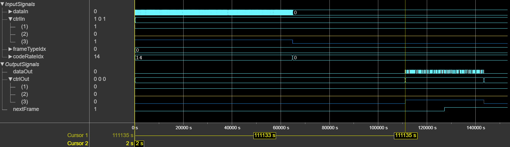
This figure shows a Logic Analyzer waveform of the sample output and latency of the
DVB-S2X LDPC Decoder block for a scalar input when you set the
FEC frame type and Code rate values to
Normal and 90/180, respectively.
The latency of the block is 1,11,133 cycles.
The latency of the block is equal to (r x t) +
d + inputLen. In this calculation, r is the number of iterations,
t is the number of clocks required to decode one iteration,
d is the pipeline delays, and inputLen is the
length of the input data.
The table shows the number of clocks the block requires to decode one iteration for normal and short frame types with different code rates and parallelism levels.
| Code Rate Index | Number of Clocks Per Iteration for Parallelism 45 | Number of Clocks Per Iteration for Parallelism 180 | ||||
|---|---|---|---|---|---|---|
| Normal | Short | Medium | Normal | Short | Medium | |
| 0 | 5579 | 1626 | 2316 | 2763 | 693 | 1445 |
| 1 | 6740 | 1527 | 2188 | 2539 | 592 | 1316 |
| 2 | 6485 | 1756 | 2413 | 2231 | 612 | 1306 |
| 3 | 6126 | 1820 | Code rate not supported for medium frame | 1890 | 666 | Code rate not supported for medium frame |
| 4 | 7039 | 2009 | 2070 | 716 | ||
| 5 | 5329 | 1583 | 1453 | 627 | ||
| 6 | 5056 | 1374 | 1437 | 412 | ||
| 7 | 5200 | 1057 | 1413 | 324 | ||
| 8 | 5332 | 1229 | 1587 | 362 | ||
| 9 | 4351 | 1113 | 1170 | 312 | ||
| 10 | 4350 | 1100 | 1155 | 728 | ||
| 11 | 4492 | 1333 | 2889 | 758 | ||
| 12 | 5133 | 1253 | 2701 | 757 | ||
| 13 | 5559 | 1745 | 2018 | 847 | ||
| 14 | 5776 | 1698 | 1875 | 715 | ||
| 15 | 6065 | 1538 | 1743 | 545 | ||
| 16 | 5849 | 1369 | 1823 | 459 | ||
| 17 | 5777 | Code rate not supported for short frame | 1716 | Code rate not supported for short frame | ||
| 18 | 6098 | 1704 | ||||
| 19 | 6098 | 1837 | ||||
| 20 | 6355 | 1918 | ||||
| 21 | 5458 | 1640 | ||||
| 22 | 5218 | 1567 | ||||
| 23 | 6162 | 1721 | ||||
| 24 | 6736 | 1867 | ||||
| 25 | 6288 | 1695 | ||||
| 26 | 5737 | 1564 | ||||
| 27 | 6255 | 1678 | ||||
| 28 | 5616 | 1518 | ||||
| 29 | 6158 | 1645 | ||||
| 30 | 6541 | 1740 | ||||
| 31 | 6133 | 1632 | ||||
| 32 | 6412 | 1691 | ||||
| 33 | 5774 | 1533 | ||||
| 34 | 6270 | 1641 | ||||
The table shows the number of pipeline delays for normal and short frame types with different code rates and parallelism levels.
| Code Rate Index | Number of Pipeline Delays for Parallelism 45 | Number of Pipeline Delays for Parallelism 180 | ||||
|---|---|---|---|---|---|---|
| Normal | Short | Medium | Normal | Short | Medium | |
| 0 | 1526 | 437 | 833 | 1519 | 430 | 826 |
| 1 | 1361 | 371 | 789 | 1354 | 364 | 782 |
| 2 | 1229 | 338 | 701 | 1222 | 331 | 694 |
| 3 | 1031 | 316 | Code rate not supported for medium frame | 1024 | 309 | Code rate not supported for medium frame |
| 4 | 833 | 239 | 826 | 232 | ||
| 5 | 701 | 206 | 694 | 199 | ||
| 6 | 536 | 173 | 529 | 166 | ||
| 7 | 437 | 151 | 430 | 144 | ||
| 8 | 371 | 129 | 364 | 122 | ||
| 9 | 261 | 96 | 254 | 89 | ||
| 10 | 239 | 415 | 232 | 408 | ||
| 11 | 1581 | 404 | 1574 | 397 | ||
| 12 | 1449 | 382 | 1442 | 375 | ||
| 13 | 1130 | 305 | 1123 | 298 | ||
| 14 | 1031 | 272 | 1024 | 265 | ||
| 15 | 965 | 250 | 958 | 243 | ||
| 16 | 932 | 184 | 925 | 177 | ||
| 17 | 921 | Code rate not supported for short frame | 914 | Code rate not supported for short frame | ||
| 18 | 877 | 870 | ||||
| 19 | 877 | 870 | ||||
| 20 | 833 | 826 | ||||
| 21 | 789 | 782 | ||||
| 22 | 756 | 749 | ||||
| 23 | 745 | 738 | ||||
| 24 | 701 | 694 | ||||
| 25 | 657 | 650 | ||||
| 26 | 646 | 639 | ||||
| 27 | 613 | 606 | ||||
| 28 | 591 | 584 | ||||
| 29 | 569 | 562 | ||||
| 30 | 569 | 562 | ||||
| 31 | 536 | 529 | ||||
| 32 | 481 | 474 | ||||
| 33 | 481 | 474 | ||||
| 34 | 327 | 320 | ||||
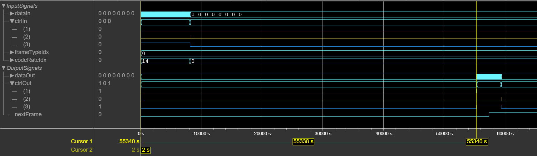
This figure shows a Logic Analyzer waveform of the sample output and latency of the
DVB-S2X LDPC Decoder block for a vector input when you set the
FEC frame type and Code rate values to
Normal and 90/180, respectively.
The latency of the block is 55,338 cycles.
The performance of the synthesized HDL code varies with the target and synthesis options. It also varies based on the type of algorithm, input type, frame type source, code rate source, decoding termination criteria, parallelism, and word length of the input LLR values.
This table shows the resource and performance data synthesis results of the block for
the supported DVB-S2X standard for scalar and vector inputs when you specify the input LLR
values in fixdt(1,4,0) format and set the Algorithm
parameter to Min-sum, the Number of
iterations parameter to 8, Parallelism
parameter to 45, and the FEC frame source parameter
to Input port. The generated HDL is targeted to the AMD®
Zynq®
UltraScale+™ MPSoC - ZCU102 Evaluation Board.
| Input Type | Slice LUTs | Slice Registers | Block RAMs | DSP | Maximum Frequency in MHz |
|---|---|---|---|---|---|
| Scalar | 13408 | 11030 | 250 | 0 | 260 |
| Vector | 15981 | 14928 | 258 | 0 | 260 |
This table shows the resource and performance data synthesis results of the block for
the supported DVB-S2X standard for scalar and vector inputs when you specify the input LLR
values in fixdt(1,4,0) format and set the Algorithm
parameter to Min-sum, the Number of
iterations parameter to 8, Parallelism
parameter to 180, and the FEC frame source parameter
to Input port. The generated HDL is targeted to the AMD
Zynq
UltraScale+ MPSoC - ZCU102 Evaluation Board.
| Input Type | Slice LUTs | Slice Registers | Block RAMs | DSP | Maximum Frequency in MHz |
|---|---|---|---|---|---|
| Scalar | 53520 | 42122 | 239 | 0 | 250 |
| Vector | 54610 | 45325 | 247 | 0 | 270 |
References
[1] ETSI Standard EN 302 307-2 V1.1.1: Digital Video Broadcasting (DVB); Second generation framing structure, channel coding and modulation systems for Broadcasting, Interactive Services, News Gathering and other broadband satellite applications, DVB-S2 Extensions (DVB-S2X),European Telecommunications Standards Institute, Valbonne, France, 2005-03.
[2] Gallager, R. “Low-Density Parity-Check Codes.” IEEE Transactions on Information Theory 8, no. 1 (January 1962): 21–28. https://doi.org/10.1109/TIT.1962.1057683.
[3] Hocevar, D.E. “A Reduced Complexity Decoder Architecture via Layered Decoding of LDPC Codes.” In IEEE Workshop On Signal Processing Systems, 2004. SIPS 2004, 107–12. Austin, Texas, USA: IEEE, 2004. https://doi.org/10.1109/SIPS.2004.1363033.
[4] Chen, Jinghu, R.M. Tanner, C. Jones, and Yan Li. "Improved Min-Sum Decoding Algorithms for Irregular LDPC Codes." In Proceedings. International Symposium on Information Theory, 2005. ISIT 2005. https://doi: 10.1109/ISIT.2005.1523374.
Extended Capabilities
HDL Coder™ provides additional configuration options that affect HDL implementation and synthesized logic.
This block has one default HDL architecture.
| ConstrainedOutputPipeline | Number of registers to place at
the outputs by moving existing delays in the design. Distributed pipelining
does not redistribute these registers. The default value is
|
| InputPipeline | Number of input pipeline stages
to insert in the generated code. Distributed pipelining and constrained
output pipelining can move these registers. The default value is
|
| OutputPipeline | Number of output pipeline stages
to insert in the generated code. Distributed pipelining and constrained
output pipelining can move these registers. The default value is
|
| SynthesisAttributes |
Specifies the synthesis attributes for the blocks and block output signals in the model. The generated HDL code contains these attributes. For more information, see SynthesisAttributes (HDL Coder). |
You cannot generate HDL code for this block inside a Resettable Synchronous Subsystem (HDL Coder).
Version History
Introduced in R2026b
See Also
DVB-S2X BCH Decoder | DVB-S2 LDPC Decoder | DVB-S2 BCH Decoder
MATLAB Command
You clicked a link that corresponds to this MATLAB command:
Run the command by entering it in the MATLAB Command Window. Web browsers do not support MATLAB commands.
Seleziona un sito web
Seleziona un sito web per visualizzare contenuto tradotto dove disponibile e vedere eventi e offerte locali. In base alla tua area geografica, ti consigliamo di selezionare: .
Puoi anche selezionare un sito web dal seguente elenco:
Come ottenere le migliori prestazioni del sito
Per ottenere le migliori prestazioni del sito, seleziona il sito cinese (in cinese o in inglese). I siti MathWorks per gli altri paesi non sono ottimizzati per essere visitati dalla tua area geografica.
Americhe
- América Latina (Español)
- Canada (English)
- United States (English)
Europa
- Belgium (English)
- Denmark (English)
- Deutschland (Deutsch)
- España (Español)
- Finland (English)
- France (Français)
- Ireland (English)
- Italia (Italiano)
- Luxembourg (English)
- Netherlands (English)
- Norway (English)
- Österreich (Deutsch)
- Portugal (English)
- Sweden (English)
- Switzerland
- United Kingdom (English)
