NR PDSCH Throughput Using Channel State Information Feedback
This reference simulation measures the physical downlink shared channel (PDSCH) throughput of a 5G new radio (NR) link. The simulation uses channel state information (CSI) feedback to adjust these downlink shared channel (DL-SCH) and PDSCH transmission parameters: target code rate, modulation, number of layers, and multiple-input multiple-output (MIMO) precoding matrix.
Introduction
This figure shows the steps of PDSCH throughput estimation in this reference simulation. The transmitter (gNodeB) includes transport channel coding stages (DL-SCH) and PDSCH generation. The transmission parameters are based on the CSI measurements that the receiver (UE) performs and feeds back to the transmitter. The aim of this mechanism is to adapt transmission parameters to the channel conditions. The simulation also controls the CSI feedback delay. For a 5G NR simulation that enables CSI compression techniques based on artificial intelligence, see the Test AI-based CSI Compression Techniques for Enhanced PDSCH Throughput example.
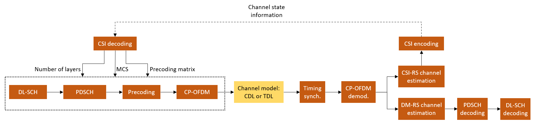
This simulation is based on the NR PDSCH Throughput example with the addition of using CSI feedback from the receiver to adjust transmission parameters.
CSI Feedback and Link Adaptation in 5G NR
User equipment (UE) uses channel state information reference signals (CSI-RS) to estimate the downlink channel response and reports a set of CSI indicators. The CSI report includes these indicators, as defined in TS 38.214 Section 5.2.2:
Rank indicator (RI)
Precoding matrix indicator (PMI)
Channel quality indicator (CQI)
The gNodeB uses the reported CSI to configure the target code rate, modulation, number of layers, and MIMO precoding matrix in subsequent PDSCH transmissions after a configurable delay. Generally, the gNodeB can select different transmission parameters from those a UE reports. However, in this simulation, the gNodeB strictly follows the recommendation from the UE. For more information on how the UE selects RI, PMI, and CQI, see the 5G NR Downlink CSI Reporting example.
The simulation assumes these conditions:
No uplink transmissions. The CSI feedback is transmitted without errors from the UE to the gNodeB.
Fixed PDSCH PRB allocation for the length of the simulation. No scheduler exists to adapt the allocation to the channel conditions.
FDD operation.
No HARQ support.
Simulation Length and SNR Points
Set the length of the simulation in terms of the number of 10 ms frames. To produce statistically meaningful throughput results, you must update the number of frames (NFrames) to a large number. Set the signal-to-noise ratio (SNR) points to simulate. The SNR for each layer is defined per resource element (RE) and includes the effect of signal and noise across all antennas. For an explanation of the SNR definition that this example uses, see the SNR Definition Used in Link Simulations example.
simParameters = struct();       % Clear simParameters variable to contain all key simulation parameters
simParameters.NFrames = 2;      % Number of 10 ms frames
simParameters.SNRIn = [-10 10]; % SNR range (dB)
Channel Estimator Configuration
The logical variable PerfectChannelEstimator controls channel estimation and synchronization behavior. When this variable is set to true, the simulation uses perfect channel estimation and synchronization. When this variable is set to false, the simulation uses practical channel estimation and synchronization based on the values of the received PDSCH demodulation reference signal (DM-RS).
simParameters.PerfectChannelEstimator =  true;
true;Simulation Diagnostics
The variable DisplaySimulationInformation controls the display of simulation information.
simParameters.DisplaySimulationInformation =  true;
true;The DisplayDiagnostics flag enables the plotting of the error vector magnitude (EVM) per layer. This plot monitors the quality of the received signal after equalization. The EVM per layer figure shows:
The EVM per layer per slot, which shows the EVM evolving with time.
The EVM per layer per resource block, which shows the EVM in frequency.
This figure evolves with the simulation and is updated with each slot. Typically, low SNR or channel fades can result in decreased signal quality (high EVM). The channel affects each layer differently. Therefore, the EVM values can differ across layers.
simParameters.DisplayDiagnostics =  false;
Carrier and PDSCH Configuration
Set waveform type, PDSCH numerology (subcarrier spacing (SCS) and cyclic prefix (CP) type), and other transmission configuration parameters.
% SCS carrier parameters
simParameters.Carrier = nrCarrierConfig;         % Carrier resource grid configuration
simParameters.Carrier.NSizeGrid = 52;            % Bandwidth in number of resource blocks
simParameters.Carrier.SubcarrierSpacing = 15;    % 15, 30, 60, 120 (kHz)
simParameters.Carrier.CyclicPrefix = 'Normal';   % 'Normal' or 'Extended' (Extended CP is relevant for 60 kHz SCS only)
simParameters.Carrier.NCellID = 1;               % Cell identity
Specify a full-band slot-wise PDSCH transmission and reserve the first 2 OFDM symbols.
simParameters.PDSCH = nrPDSCHConfig; % This PDSCH definition is the basis for all PDSCH transmissions in the simulation % Define PDSCH time allocation in a slot simParameters.PDSCH.MappingType ="A"; % PDSCH mapping type ("A" (slot-wise), "B" (nonslot-wise)) symAlloc = [2 simParameters.Carrier.SymbolsPerSlot-2]; % Starting symbol and number of symbols of each PDSCH allocation simParameters.PDSCH.SymbolAllocation = symAlloc; % Define PDSCH frequency resource allocation per slot to be full grid simParameters.PDSCH.PRBSet = 0:simParameters.Carrier.NSizeGrid-1; % Scrambling identifiers simParameters.PDSCH.NID = simParameters.Carrier.NCellID; simParameters.PDSCH.RNTI = 1;
Specify the DM-RS configuration, as defined in TS 38.211 Section 7.4.1.1. The example dynamically sets the DM-RS port set based on the CSI feedback (RI) and DM-RS configuration. For more information on valid DM-RS port set configurations, see the DMRSPortSet object property or TS 38.211 Table 7.4.1.1.2-5.
simParameters.PDSCH.DMRS.DMRSTypeAPosition =2; % Mapping type A only. First DM-RS symbol position (2, 3) simParameters.PDSCH.DMRS.DMRSLength =
2; % Number of front-loaded DM-RS symbols (1 (single symbol), 2 (double symbol)) simParameters.PDSCH.DMRS.DMRSAdditionalPosition =
1; % Additional DM-RS symbol positions (max range 0...3) simParameters.PDSCH.DMRS.DMRSConfigurationType =
2; % DM-RS configuration type (1, 2) simParameters.PDSCH.DMRS.NumCDMGroupsWithoutData =
3; % CDM groups without data (1, 2, 3)
Specify additional simulation parameters for the DL-SCH and PDSCH. Set the frequency granularity of the MIMO precoder, as defined in TS 38.214 Section 5.1.2.3, the modulation and coding scheme table, as defined in TS 38.214 Section 5.1.3.1, and the overhead for transport block size calculation. Set XOverhead to empty ([]) for automatic selection based on the REs allocated for the CSI-RS. The example then selects a value for XOverhead that is suitable for slots with CSI-RS transmissions.
simParameters.PDSCHExtension = struct(); simParameters.PDSCHExtension.PRGBundleSize =4; % 2, 4, or [] to signify "wideband" simParameters.PDSCHExtension.MCSTable =
'Table1'; % 'Table1', ..., 'Table4' simParameters.PDSCHExtension.XOverhead =
[ ]; % 0, 6, 12, 18, or [] for automatic selection.
Configure the LDPC decoding algorithm and maximum LDPC iterations. The available decoding algorithms are 'Belief propagation', 'Layered belief propagation', 'Normalized min-sum', and 'Offset min-sum'.
simParameters.PDSCHExtension.LDPCDecodingAlgorithm = "Normalized min-sum";
simParameters.PDSCHExtension.MaximumLDPCIterationCount = 6;
"Normalized min-sum";
simParameters.PDSCHExtension.MaximumLDPCIterationCount = 6;Antenna Panel Configuration
Configure the antenna panel geometry by specifying the number of antenna panels () and their dimensions ( and ). and are the number of cross-polarized antenna elements in horizontal and vertical directions for each panel, respectively, and is the number of column array panels. This diagram shows an antenna panel arrangement and its dimensions.
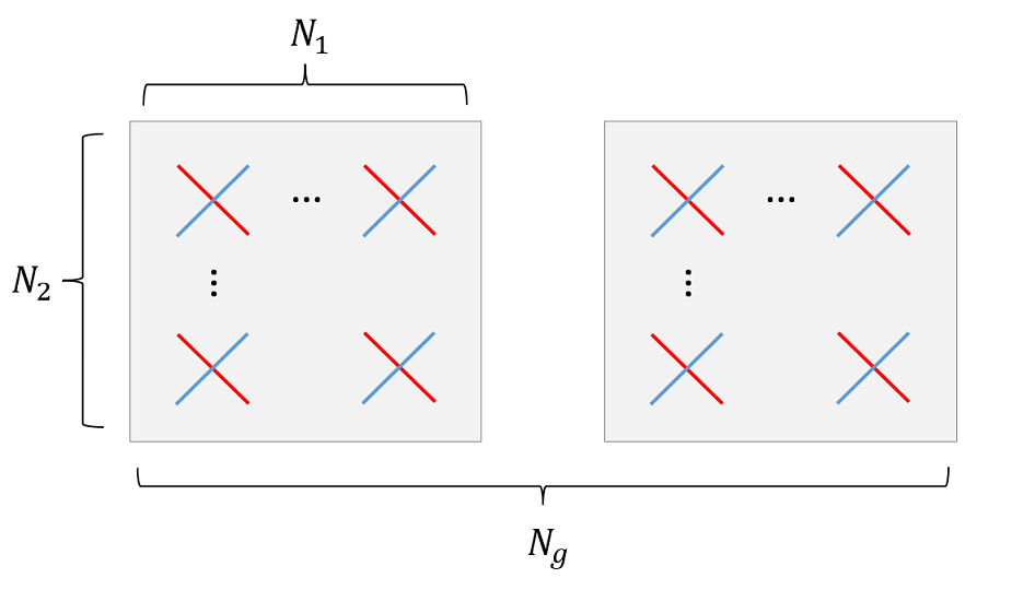
The MIMO precoding codebooks defined in TS 38.214 Section 5.2.2.2 restrict the values of , , and that 5G NR supports. To configure single-input single-output (SISO) transmissions with single-polarized antenna elements, set the panel dimensions to [1 1] and the number of polarizations to 1. The receiver panel dimensions are not limited by the codebooks.
simParameters.TransmitAntennaArray.NumPanels =1; % Number of transmit panels in horizontal dimension (Ng) simParameters.TransmitAntennaArray.PanelDimensions =
[2 2]; % Number of columns and rows in the transmit panel (N1, N2) simParameters.TransmitAntennaArray.NumPolarizations =
2; % Number of transmit polarizations simParameters.ReceiveAntennaArray.NumPanels =
1; % Number of receive panels in horizontal dimension (Ng) simParameters.ReceiveAntennaArray.PanelDimensions = [2 1]; % Number of columns and rows in the receive panel (N1, N2) simParameters.ReceiveAntennaArray.NumPolarizations =
2; % Number of receive polarizations
Ensure that a transmit antenna array with more than one element is configured with two different polarizations.
simParameters.TransmitAntennaArray = validateAntennaPolarization(simParameters.TransmitAntennaArray);
The overall number of antennas is , where is the number of polarizations.
simParameters.NTxAnts = numAntennaElements(simParameters.TransmitAntennaArray);
simParameters.NRxAnts = numAntennaElements(simParameters.ReceiveAntennaArray);

disp("Number of transmit antenna elements: " + simParameters.NTxAnts)
Number of transmit antenna elements: 8
disp("Number of receive antenna elements: " + simParameters.NRxAnts)Number of receive antenna elements: 4
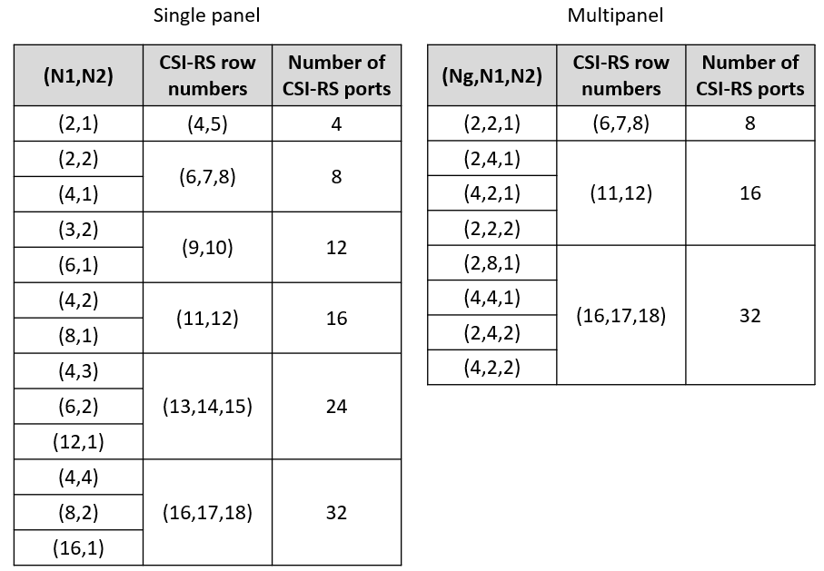
CSI-RS Configuration
The simulation configures an 8-port CSI-RS, which maps to each antenna element of the transmit panel. The number of CSI-RS ports must match the transmit array panel dimensions, as defined in TS 38.214 Table 5.2.2.2.1-2 for single-panel and Table 5.2.2.2.2-1 for multi-panel codebooks. These tables show what CSI-RS row numbers are compatible with the selected array panel dimensions. The CSI-RS row numbers are defined in TS 38.211 Table 7.4.1.5.3-1.
Set CSI-RS parameters such as the transmission periodicity and frequency density. The example automatically sets the bandwidth, row number, subcarrier locations, and symbol locations of the CSI-RS based on the specified carrier, PDSCH, and transmit antenna panel configurations. You can also specify these parameters manually.
simParameters.CSIRS = nrCSIRSConfig; simParameters.CSIRS.CSIRSPeriod = [10 0]; simParameters.CSIRS.Density ="one"; % Set CSI-RS allocation parameters simParameters.CSIRS.NumRB = simParameters.Carrier.NSizeGrid; [rowNumber, subcarriers, symbols, density] = csirsAllocationParameters(simParameters); simParameters.CSIRS.RowNumber = rowNumber; simParameters.CSIRS.SubcarrierLocations = subcarriers; simParameters.CSIRS.SymbolLocations = symbols; simParameters.CSIRS.Density = density; disp(['Number of CSI-RS ports: ' num2str(simParameters.CSIRS.NumCSIRSPorts) '.'])
Number of CSI-RS ports: 8.
csirsCDMLengths = getCSIRSCDMLengths(simParameters.CSIRS);

% Check that the number of CSI-RS ports and transmit antenna elements match
% and the consistency of multiple CSI-RS resources
validateCSIRSConfig(simParameters.Carrier,simParameters.CSIRS,simParameters.NTxAnts);
CSI Feedback Configuration
Specify the CSI feedback mode as 'RI-PMI-CQI' or 'Perfect CSI'. In both modes, the UE can perform perfect or practical channel estimation using CSI-RS.
RI-PMI-CQI: The UE selects and reports the appropriate RI, PMI, and CQI periodically. The gNodeB follows the reported CSI to configure the target code rate, modulation, number of layers, and MIMO precoding matrix in subsequent PDSCH transmissions after a configurable delay.
Perfect CSI: The UE reports channel estimates to the gNodeB periodically. The gNodeB selects the MIMO precoding matrix from the Eigenvectors of the channel estimates and a suitable modulation and coding scheme (MCS) from TS 38.214 Table 5.1.3.1-1, conditioned on the selected MIMO precoder. Then the gNodeB applies the selected configuration in a subsequent PDSCH transmission after a configurable delay.
simParameters.CSIReportMode ='RI-PMI-CQI'; % 'RI-PMI-CQI', 'Perfect CSI'
Specify the CSI report configuration. For more information on the CSI report configuration, see the 5G NR Downlink CSI Reporting example.
simParameters.CSIReportConfig = struct(); simParameters.CSIReportConfig.Period = [5 0]; % Periodicity and offset of the CSI report in slots simParameters.CSIReportConfig.CQITable ="Table1"; % 'Table1', 'Table2', 'Table3' simParameters.CSIReportConfig.CQIMode =
'Wideband'; % 'Wideband', 'Subband' simParameters.CSIReportConfig.PMIMode =
'Subband'; % 'Wideband', 'Subband' simParameters.CSIReportConfig.CodebookType =
'Type1SinglePanel'; % 'Type1SinglePanel', 'Type1MultiPanel', 'Type2', 'eType2' simParameters.CSIReportConfig.SubbandSize =
4; % Subband size in RB (4, 8, 16, 32) simParameters.CSIReportConfig.CodebookMode =
1; % 1, 2 simParameters.CSIReportConfig.RIRestriction = []; % Empty for no rank restriction simParameters.CSIReportConfig.NumberOfBeams =
2; % 2, 3, 4. Only for Type II codebooks simParameters.CSIReportConfig.PhaseAlphabetSize =
8; % 4, 8. Only for Type II codebooks simParameters.CSIReportConfig.SubbandAmplitude =
true; % true, false. Only for Type II codebooks simParameters.CSIReportConfig.ParameterCombination =
1; % 1...8. Only for Enhanced Type II codebooks simParameters.CSIReportConfig.NumberOfPMISubbandsPerCQISubband =
1; % 1, 2. Only for Enhanced Type II codebooks simParameters.CSIReportConfig.NStartBWP = []; % Empty to signal the entire carrier simParameters.CSIReportConfig.NSizeBWP = []; % Empty to signal the entire carrier % Configure the CSI report with the antenna panel dimensions specified simParameters.CSIReportConfig = updateCSIReportPanelInfo(simParameters.CSIReportConfig,simParameters.TransmitAntennaArray); % Adjust the rank restriction based on the number of ports supported by % the DM-RS configuration, as defined in TS 38.211 Table 7.4.1.1.2-5. simParameters.CSIReportConfig.RIRestriction = updateRankRestriction(simParameters.PDSCH.DMRS,simParameters.CSIReportConfig);
Configure the CSI processing delay in slots. For the UE, this delay is the number of time slots between the reception of the CSI-RS and the availability of the CSI feedback. For the gNodeB, the delay is the number of time slots between the reception of the CSI report and the transmission using the recommended CSI.
simParameters.UEProcessingDelay = 7;
simParameters.BSProcessingDelay = 1;
Propagation Channel Configuration
Configure the delay profile, delay spread, and maximum Doppler shift of the propagation channel for the simulation. Both CDL and TDL channel models are supported. The panel dimensions and cross-polarized elements specified in Antenna Panel Configuration define the geometry of the antenna arrays for CDL channels.
simParameters.DelayProfile = 'CDL-C';   % 'CDL-A', ..., 'CDL-E', 'TDL-A', ..., 'TDL-E'
simParameters.DelaySpread = 300e-9;     % s
simParameters.MaximumDopplerShift = 5;  % Hz

simParameters.Channel = createChannel(simParameters);
Processing Loop
To determine the PDSCH throughput for each SNR point, the simulation performs these steps:
Update DL-SCH and PDSCH transmission parameters (target code rate, number of layers, modulation, and MIMO precoding matrix). This step applies only when a new CSI report is available.
Map CSI-RS signals to the resource grid.
Perform channel coding (DL-SCH) and PDSCH encoding. Map PDSCH and PDSCH DM-RS to the resource grid.
OFDM modulate the generated grid.
Pass the signal through a fading channel with AWGN.
Perform synchronization and OFDM demodulation.
Perform PDSCH DM-RS based channel estimation.
Perform equalization.
Decode the PDSCH and DL-SCH, and measure the PDSCH throughput.
Perform CSI-RS based channel estimation.
Create CSI report.
Feed the CSI report back to the transmitter with the appropriate delay.
To reduce the total simulation time, you can execute the SNR loop in parallel by using the Parallel Computing Toolbox™. Comment out the for statement and uncomment the parfor statement. If the Parallel Computing Toolbox is not installed, parfor defaults to normal for statement. Because parfor-loop iterations are executed in parallel in a nondeterministic order, the simulation information displayed for each SNR point can be intertwined. To switch off simulation information display, set the displaySimulationInformation variable above to false.
% Array to store the maximum throughput for all SNR points
maxThroughput = zeros(length(simParameters.SNRIn),1);
% Array to store the simulation throughput for all SNR points
simThroughput = zeros(length(simParameters.SNRIn),1);

% Cell array to store CSI reports per SNR point
CSIReport = {};

for snrIdx = 1:numel(simParameters.SNRIn)
% parfor snrIdx = 1:numel(simParameters.SNRIn)
% To reduce the total simulation time, you can execute this loop in
% parallel by using the Parallel Computing Toolbox. Comment out the 'for'
% statement and uncomment the 'parfor' statement.

    % Reset the random number generator for repeatability
    rng(0,"twister");

    % Display simulation information at this SNR point
    displaySNRPointProgress(simParameters,snrIdx);

    % Take full copies of the simulation-level parameter structures so that
    % they are not PCT broadcast variables when using parfor
    simParamLocal = simParameters;

    % Extract CSI feedback configuration parameters
    csiFeedbackOpts = getCSIFeedbackOptions(simParamLocal);

    % Set up the transmitter, propagation channel, and receiver
    [carrier,encodeDLSCH,pdsch,pdschextra,csirs,wtx] = setupTransmitter(simParamLocal);
    [channel,maxChDelay] = setupChannel(simParamLocal);
    [decodeDLSCH,timingOffset,N0,noiseEst,csiReports,csiSlots] = setupReceiver(simParamLocal,channel,snrIdx,csiFeedbackOpts);

    % Total number of slots in the simulation period
    NSlots = simParamLocal.NFrames * carrier.SlotsPerFrame;

    % Loop over the entire waveform length
    for nslot = 0:NSlots-1

        % Update the carrier slot numbers for new slot
        carrier.NSlot = nslot;

        % Use new CSI report to configure the number of layers and
        % modulation of the PDSCH and target code rate of the DL-SCH if
        % there is a new report available.
        [isNewReport,repIdx] = ismember(nslot,csiSlots);
        if isNewReport
            [pdsch.Modulation,pdschextra.TargetCodeRate,wtx] = hCSIDecode(carrier,pdsch,pdschextra,csiReports(repIdx),csiFeedbackOpts);
            pdsch.NumLayers = size(wtx,1);
            encodeDLSCH.TargetCodeRate = pdschextra.TargetCodeRate;
        end

        % Create an OFDM resource grid for a slot
        dlGrid = nrResourceGrid(carrier,csirs.NumCSIRSPorts);

        % CSI-RS mapping to the slot resource grid
        [csirsInd,csirsInfo] = nrCSIRSIndices(carrier,csirs);
        csirsSym = nrCSIRS(carrier,csirs);
        dlGrid(csirsInd) = csirsSym;
        csirsTransmission = ~isempty(csirsInd);

        % PDSCH reserved REs for CSI-RS
        pdsch.ReservedRE = csirsInd-1; % 0-based indices

        % PDSCH generation
        % Calculate the transport block sizes for the transmission in the slot
        [pdschIndices,pdschIndicesInfo] = nrPDSCHIndices(carrier,pdsch);
        trBlkSizes = nrTBS(pdsch.Modulation,pdsch.NumLayers,numel(pdsch.PRBSet),pdschIndicesInfo.NREPerPRB,pdschextra.TargetCodeRate,pdschextra.XOverhead);

        % Transport block generation
        for cwIdx = 1:pdsch.NumCodewords
            % New data for current codeword then create a new DL-SCH transport block
            trBlk = randi([0 1],trBlkSizes(cwIdx),1);
            setTransportBlock(encodeDLSCH,trBlk,cwIdx-1);
            resetSoftBuffer(decodeDLSCH,cwIdx-1);
        end

        % Encode the DL-SCH transport blocks
        RV = zeros(1,pdsch.NumCodewords);
        codedTrBlocks = encodeDLSCH(pdsch.Modulation,pdsch.NumLayers, ...
            pdschIndicesInfo.G,RV);

        % PDSCH modulation and precoding
        pdschSymbols = nrPDSCH(carrier,pdsch,codedTrBlocks);
        [pdschAntSymbols,pdschAntIndices] = nrPDSCHPrecode(carrier,pdschSymbols,pdschIndices,wtx);
        dlGrid(pdschAntIndices) = pdschAntSymbols;

        % PDSCH DM-RS precoding and mapping
        dmrsSymbols = nrPDSCHDMRS(carrier,pdsch);
        dmrsIndices = nrPDSCHDMRSIndices(carrier,pdsch);
        [dmrsAntSymbols,dmrsAntIndices] = nrPDSCHPrecode(carrier,dmrsSymbols,dmrsIndices,wtx);
        dlGrid(dmrsAntIndices) = dmrsAntSymbols;

        % Warn if CSI-RS and PDSCH DM-RS resources overlap
        if any(ismember(dmrsIndices,csirsInd))
            warning("CSI-RS and PDSCH DM-RS resources overlap in the resource grid. This can result in decoding failures.")
        end

        % OFDM modulation
        txWaveform = nrOFDMModulate(carrier,dlGrid);

        % Pass data through channel model. Append zeros at the end of the
        % transmitted waveform to flush channel content. These zeros take
        % into account any delay introduced in the channel.
        txWaveform = [txWaveform; zeros(maxChDelay,size(txWaveform,2))]; %#ok<AGROW>
        [rxWaveform,ofdmResponse,tOffset] = channel(txWaveform,carrier);

        % Add AWGN to the received time-domain waveform
        noise = N0*randn(size(rxWaveform),"like",1i);
        rxWaveform = rxWaveform + noise;

        if simParamLocal.PerfectChannelEstimator
            % For perfect synchronization, use the timing offset obtained
            % from the channel
            timingOffset = tOffset;
        else
            % Practical synchronization. Correlate the received waveform
            % with the PDSCH DM-RS to obtain the timing offset and
            % correlation magnitude. The receiver updates the timing offset
            % only when the correlation magnitude is high.
            [t,mag] = nrTimingEstimate(carrier,rxWaveform,dmrsIndices,dmrsSymbols);
            timingOffset = hSkipWeakTimingOffset(timingOffset,t,mag);
            % Display a warning if the estimated timing offset exceeds the
            % maximum channel delay
            if timingOffset > maxChDelay
                warning(['Estimated timing offset (%d) is greater than the maximum channel delay (%d).' ...
                    ' This can result in a decoding failure. This issue can be caused by low SNR' ...
                    ' or not enough DM-RS symbols for successful synchronization.'],timingOffset,maxChDelay);
            end
        end
        rxWaveform = rxWaveform(1+timingOffset:end,:);

        % Perform OFDM demodulation on the received data to recreate the
        % resource grid, including padding in the event that practical
        % synchronization results in an incomplete slot being demodulated
        rxGrid = nrOFDMDemodulate(carrier,rxWaveform);
        [K,L,R] = size(rxGrid);
        if (L < carrier.SymbolsPerSlot)
            rxGrid = cat(2,rxGrid,zeros(K,carrier.SymbolsPerSlot-L,R));
        end

        if simParamLocal.PerfectChannelEstimator
            % For perfect channel estimate, use the OFDM channel response
            % obtained from the channel
            Hest = ofdmResponse;

            % Get PDSCH resource elements from the received grid and
            % channel estimate
            [pdschRx,pdschHest,~,pdschHestIndices] = nrExtractResources(pdschIndices,rxGrid,Hest);

            % Apply precoding to channel estimate
            pdschHest = nrPDSCHPrecode(carrier,pdschHest,pdschHestIndices,permute(wtx,[2 1 3]));
        else
            % Practical channel estimation between the received grid and
            % each transmission layer, using the PDSCH DM-RS for each
            % layer. This channel estimate includes the effect of
            % transmitter precoding
            aw = channelEstimateAveragingWindow(pdsch);
            [Hest,noiseEst] = nrChannelEstimate(carrier,rxGrid,dmrsIndices,dmrsSymbols,...
                PRGBundleSize = pdschextra.PRGBundleSize,CDMLengths = pdsch.DMRS.CDMLengths,AveragingWindow = aw);

            % Average noise estimate across PRGs and layers
            noiseEst = mean(noiseEst,'all');

            % Get PDSCH resource elements from the received grid and
            % channel estimate
            [pdschRx,pdschHest] = nrExtractResources(pdschIndices,rxGrid,Hest);
        end

        % Equalization
        [pdschEq,eqCSIScaling] = nrEqualizeMMSE(pdschRx,pdschHest,noiseEst);

        % Decode PDSCH physical channel
        [dlschLLRs,rxSymbols] = nrPDSCHDecode(carrier,pdsch,pdschEq,noiseEst);

        % Display EVM per layer, per slot and per RB
        if (simParamLocal.DisplayDiagnostics)
            plotLayerEVM(NSlots,nslot,pdsch,size(dlGrid),pdschIndices,pdschSymbols,pdschEq);
        end

        % Scale LLRs
        eqCSIScaling = nrLayerDemap(eqCSIScaling); % CSI scaling layer demapping
        for cwIdx = 1:pdsch.NumCodewords
            Qm = length(dlschLLRs{cwIdx})/length(rxSymbols{cwIdx});        % bits per symbol
            eqCSIScaling{cwIdx} = repmat(eqCSIScaling{cwIdx}.',Qm,1);      % expand by each bit per symbol
            dlschLLRs{cwIdx} = dlschLLRs{cwIdx} .* eqCSIScaling{cwIdx}(:); % scale LLRs
        end

        % Decode the DL-SCH transport channel
        decodeDLSCH.TransportBlockLength = trBlkSizes;
        decodeDLSCH.TargetCodeRate = pdschextra.TargetCodeRate;
        [decbits,blkerr] = decodeDLSCH(dlschLLRs,pdsch.Modulation,pdsch.NumLayers,RV);

        % Store values to calculate throughput
        simThroughput(snrIdx) = simThroughput(snrIdx) + sum(~blkerr .* trBlkSizes);
        maxThroughput(snrIdx) = maxThroughput(snrIdx) + sum(trBlkSizes);

        % CSI measurements and encoding
        if csirsTransmission

            if ~simParamLocal.PerfectChannelEstimator
                % Consider only the NZP-CSI-RS symbols and indices for CSI-RS based
                % channel estimation
                nzpind = (csirsSym ~= 0);

                % Calculate practical channel estimate based on CSI-RS. Use
                % a time-averaging window that covers all of the
                % transmitted CSI-RS symbols.
                [Hest,noiseEst] = nrChannelEstimate(carrier,rxGrid, ...
                    csirsInd(nzpind),csirsSym(nzpind),'CDMLengths',csirsCDMLengths);
            end

            % Generate CSI report. Store the report for use at the
            % transmitter. The CSI feedback is subject to a delay that
            % depends on the CSI report periodicity and the UE processing
            % delay. The slot in which the CSI is available to use at the
            % transmitter depends on the BS processing delay as well.
            csiReport = hCSIEncode(carrier,csirs,Hest,noiseEst,csiFeedbackOpts);
            feedbackSlot = nextCSISlot(csiFeedbackOpts.CSIReportPeriod,1+nslot+simParamLocal.UEProcessingDelay);
            csiSlots(end+1) = 1+feedbackSlot+simParamLocal.BSProcessingDelay; %#ok<SAGROW>
            csiReports(end+1) = csiReport; %#ok<SAGROW>

            csiReports = reduceCSIReports(csiReports,csiSlots,carrier.NSlot,simParamLocal.CSIReportMode);
        end

        % Print slot-wise information
        if simParamLocal.DisplaySimulationInformation
            printSlotInfo(NSlots,carrier,pdsch,pdschextra,blkerr,trBlkSizes./pdschIndicesInfo.G,csirsTransmission,csiReports,repIdx)
        end
    end

    % Store CSI report for each SNR point
    CSIReport{snrIdx} = csiReports; %#ok<SAGROW>

    % Display the results dynamically in the command window
    if simParamLocal.DisplaySimulationInformation
        fprintf('\n');
    end
    fprintf('\nThroughput(Mbps) for %d frame(s) = %.4f\n',simParamLocal.NFrames,1e-6*simThroughput(snrIdx)/(simParamLocal.NFrames*10e-3));

end
Simulating transmission scheme 1 (8x4) and SCS=15kHz with CDL-C channel at -10dB SNR for 2 10ms frame(s)
Using RI, PMI, and CQI as CSI feedback.
( 5.00%) NSlot= 0: Transmission succeeded (Layers=1, Mod=16QAM, TCR=0.479, CR=0.462). Using initial CSI. CSI-RS transmission.
(10.00%) NSlot= 1: Transmission succeeded (Layers=1, Mod=16QAM, TCR=0.479, CR=0.423).
(15.00%) NSlot= 2: Transmission succeeded (Layers=1, Mod=16QAM, TCR=0.479, CR=0.423).
(20.00%) NSlot= 3: Transmission succeeded (Layers=1, Mod=16QAM, TCR=0.479, CR=0.423).
(25.00%) NSlot= 4: Transmission succeeded (Layers=1, Mod=16QAM, TCR=0.479, CR=0.423).
(30.00%) NSlot= 5: Transmission succeeded (Layers=1, Mod=16QAM, TCR=0.479, CR=0.423).
(35.00%) NSlot= 6: Transmission succeeded (Layers=1, Mod=16QAM, TCR=0.479, CR=0.423).
(40.00%) NSlot= 7: Transmission succeeded (Layers=1, Mod=16QAM, TCR=0.479, CR=0.423).
(45.00%) NSlot= 8: Transmission succeeded (Layers=1, Mod=16QAM, TCR=0.479, CR=0.423).
(50.00%) NSlot= 9: Transmission succeeded (Layers=1, Mod=16QAM, TCR=0.479, CR=0.423).
(55.00%) NSlot=10: Transmission succeeded (Layers=1, Mod=16QAM, TCR=0.479, CR=0.462). CSI-RS transmission.
(60.00%) NSlot=11: Transmission succeeded (Layers=1, Mod=16QAM, TCR=0.479, CR=0.423).
(65.00%) NSlot=12: Transmission succeeded (Layers=1, Mod=16QAM, TCR=0.479, CR=0.423). Using CSI from NSlot= 0.
(70.00%) NSlot=13: Transmission succeeded (Layers=1, Mod=16QAM, TCR=0.479, CR=0.423).
(75.00%) NSlot=14: Transmission succeeded (Layers=1, Mod=16QAM, TCR=0.479, CR=0.423).
(80.00%) NSlot=15: Transmission succeeded (Layers=1, Mod=16QAM, TCR=0.479, CR=0.423).
(85.00%) NSlot=16: Transmission succeeded (Layers=1, Mod=16QAM, TCR=0.479, CR=0.423).
(90.00%) NSlot=17: Transmission succeeded (Layers=1, Mod=16QAM, TCR=0.479, CR=0.423).
(95.00%) NSlot=18: Transmission succeeded (Layers=1, Mod=16QAM, TCR=0.479, CR=0.423).
(100.00%) NSlot=19: Transmission succeeded (Layers=1, Mod=16QAM, TCR=0.479, CR=0.423).
Throughput(Mbps) for 2 frame(s) = 8.4560
Simulating transmission scheme 1 (8x4) and SCS=15kHz with CDL-C channel at 10dB SNR for 2 10ms frame(s)
Using RI, PMI, and CQI as CSI feedback.
( 5.00%) NSlot= 0: Transmission succeeded (Layers=3, Mod=64QAM, TCR=0.650, CR=0.622). Using initial CSI. CSI-RS transmission.
(10.00%) NSlot= 1: Transmission succeeded (Layers=3, Mod=64QAM, TCR=0.650, CR=0.570).
(15.00%) NSlot= 2: Transmission succeeded (Layers=3, Mod=64QAM, TCR=0.650, CR=0.570).
(20.00%) NSlot= 3: Transmission succeeded (Layers=3, Mod=64QAM, TCR=0.650, CR=0.570).
(25.00%) NSlot= 4: Transmission succeeded (Layers=3, Mod=64QAM, TCR=0.650, CR=0.570).
(30.00%) NSlot= 5: Transmission succeeded (Layers=3, Mod=64QAM, TCR=0.650, CR=0.570).
(35.00%) NSlot= 6: Transmission succeeded (Layers=3, Mod=64QAM, TCR=0.650, CR=0.570).
(40.00%) NSlot= 7: Transmission succeeded (Layers=3, Mod=64QAM, TCR=0.650, CR=0.570).
(45.00%) NSlot= 8: Transmission succeeded (Layers=3, Mod=64QAM, TCR=0.650, CR=0.570).
(50.00%) NSlot= 9: Transmission succeeded (Layers=3, Mod=64QAM, TCR=0.650, CR=0.570).
(55.00%) NSlot=10: Transmission succeeded (Layers=3, Mod=64QAM, TCR=0.650, CR=0.622). CSI-RS transmission.
(60.00%) NSlot=11: Transmission succeeded (Layers=3, Mod=64QAM, TCR=0.650, CR=0.570).
(65.00%) NSlot=12: Transmission succeeded (Layers=3, Mod=64QAM, TCR=0.650, CR=0.570). Using CSI from NSlot= 0.
(70.00%) NSlot=13: Transmission succeeded (Layers=3, Mod=64QAM, TCR=0.650, CR=0.570).
(75.00%) NSlot=14: Transmission succeeded (Layers=3, Mod=64QAM, TCR=0.650, CR=0.570).
(80.00%) NSlot=15: Transmission succeeded (Layers=3, Mod=64QAM, TCR=0.650, CR=0.570).
(85.00%) NSlot=16: Transmission succeeded (Layers=3, Mod=64QAM, TCR=0.650, CR=0.570).
(90.00%) NSlot=17: Transmission succeeded (Layers=3, Mod=64QAM, TCR=0.650, CR=0.570).
(95.00%) NSlot=18: Transmission succeeded (Layers=3, Mod=64QAM, TCR=0.650, CR=0.570).
(100.00%) NSlot=19: Transmission succeeded (Layers=3, Mod=64QAM, TCR=0.650, CR=0.570).
Throughput(Mbps) for 2 frame(s) = 51.2160
Results
Display the measured throughput as a function of the SNR.
figure;
plot(simParameters.SNRIn,1e-6*simThroughput/(simParameters.NFrames*10e-3),'o-.')

xlabel('SNR (dB)'); ylabel('Throughput (Mbps)'); grid on;
title(sprintf('%s (%dx%d) / NRB=%d / SCS=%dkHz / CSI: %s', ...
              simParameters.DelayProfile,simParameters.NTxAnts,simParameters.NRxAnts, ...
              simParameters.Carrier.NSizeGrid,simParameters.Carrier.SubcarrierSpacing,...
              char(simParameters.CSIReportMode)));

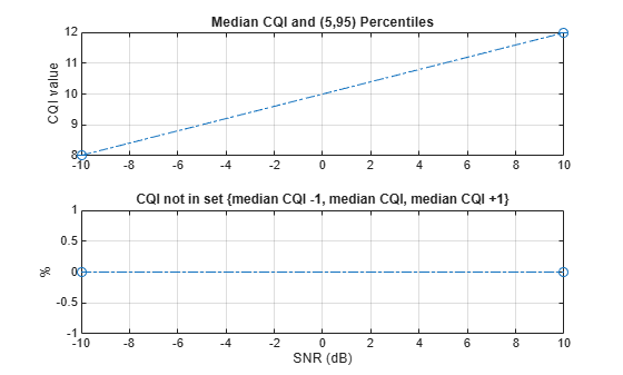
if simParameters.CSIReportMode == "RI-PMI-CQI"
    perc = 90;
    plotCQI(simParameters,CSIReport,perc)
end
% Bundle key parameters and results into a combined structure for recording
simResults.simParameters = simParameters;
simResults.simThroughput = simThroughput;
simResults.maxThroughput = maxThroughput;
simResults.CSIReport = CSIReport;
Local Functions
function [carrier,eDLSCH,pdsch,pdschextra,csirs,wtx] = setupTransmitter(simParameters)
% Extract channel and signal-level parameters, create DL-SCH encoder, and
% initialize MIMO precoding matrix.

    carrier = simParameters.Carrier;
    pdsch = simParameters.PDSCH;
    pdschextra = simParameters.PDSCHExtension;
    csirs = simParameters.CSIRS;

    % Select XOverhead for TBS calculation if required
    if isempty(pdschextra.XOverhead)
        pdschextra.XOverhead = getXOverhead(carrier,csirs);
    end

    % Create DL-SCH encoder system object to perform transport channel
    % encoding
    eDLSCH = nrDLSCH;

    % Initialize MIMO precoding matrix
    wtx = 1;

end

function [decodeDLSCH,timingOffset,N0,noiseEst,csiReports,csiAvailableSlots] = setupReceiver(simParameters,channel,snrIdx,csiFeedbackOpts)
% Create and configure DL-SCH decoder. Obtain noise related quantities and
% initial CSI feedback from perfect channel knowledge.

    % Create DL-SCH decoder system object to perform transport channel
    % decoding
    decodeDLSCH = nrDLSCHDecoder;
    decodeDLSCH.LDPCDecodingAlgorithm = simParameters.PDSCHExtension.LDPCDecodingAlgorithm;
    decodeDLSCH.MaximumLDPCIterationCount = simParameters.PDSCHExtension.MaximumLDPCIterationCount;

    % Calculate noise standard deviation. Normalize noise power by the IFFT
    % size used in OFDM modulation, as the OFDM modulator applies this
    % normalization to the transmitted waveform.
    carrier = simParameters.Carrier;
    waveInfo = nrOFDMInfo(carrier);
    SNRdB = simParameters.SNRIn(snrIdx);
    SNR = 10^(SNRdB/10);
    N0 = 1/sqrt(double(waveInfo.Nfft)*SNR);

    % Also normalize by the number of receive antennas if the channel
    % applies this normalization to the output
    chInfo = info(channel);
    if channel.NormalizeChannelOutputs
        if contains(simParameters.DelayProfile,'CDL')
            N0 = N0/sqrt(chInfo.NumOutputSignals);
        else
            N0 = N0/sqrt(chInfo.NumReceiveAntennas);
        end
    end

    % Initial channel estimate
    [Hest,timingOffset] = getInitialChannelEstimate(carrier,channel,chInfo.MaximumChannelDelay);

    % Initial noise variance
    noiseEst = N0^2*double(waveInfo.Nfft);

    % Obtain an initial CSI report based on perfect channel estimates that
    % the Tx can use to adapt the transmission parameters.
    csirs = simParameters.CSIRS;

    % Initial CSI report using initial channel estimate
    csiFeedbackOpts.PerfectChannelEstimator = true;
    csirs.CSIRSPeriod = 'on';
    csiReports = hCSIEncode(carrier,csirs,Hest,noiseEst,csiFeedbackOpts);
    csiAvailableSlots = 0;

end

function channel = createChannel(simParameters)
% Create and configure the propagation channel. If the number of antennas
% is 1, configure only 1 polarization, otherwise configure 2 polarizations.

    if contains(simParameters.DelayProfile,'CDL')

        % Create CDL channel
        channel = nrCDLChannel;

        % Tx antenna array configuration in CDL channel. The number of antenna
        % elements depends on the panel dimensions. The size of the antenna
        % array is [M,N,P,Mg,Ng]. M and N are the number of rows and columns in
        % the antenna array. P is the number of polarizations (1 or 2). Mg and
        % Ng are the number of row and column array panels respectively. Note
        % that N1 and N2 in the panel dimensions follow a different convention
        % and denote the number of columns and rows, respectively.
        txArray = simParameters.TransmitAntennaArray;
        M = txArray.PanelDimensions(2);
        N = txArray.PanelDimensions(1);
        Ng = txArray.NumPanels;
        P = txArray.NumPolarizations;

        channel.TransmitAntennaArray.Size = [M N P 1 Ng];
        channel.TransmitAntennaArray.ElementSpacing = [0.5 0.5 1 N/2]; % Element spacing in wavelengths
        channel.TransmitAntennaArray.PolarizationAngles = [-45 45];  % Polarization angles in degrees

        % Rx antenna array configuration in CDL channel
        rxArray = simParameters.ReceiveAntennaArray;
        M = rxArray.PanelDimensions(2);
        N = rxArray.PanelDimensions(1);
        Ng = rxArray.NumPanels;
        P = rxArray.NumPolarizations;

        channel.ReceiveAntennaArray.Size = [M N P 1 Ng];
        channel.ReceiveAntennaArray.ElementSpacing = [0.5 0.5 1 N/2];  % Element spacing in wavelengths
        channel.ReceiveAntennaArray.PolarizationAngles = [0 90];     % Polarization angles in degrees

    elseif contains(simParameters.DelayProfile,'TDL')

        channel = nrTDLChannel;
        channel.NumTransmitAntennas = simParameters.NTxAnts;
        channel.NumReceiveAntennas = simParameters.NRxAnts;

    else

        error('Channel not supported.')

    end

    % Configure common channel parameters: delay profile, delay spread, and
    % maximum Doppler shift
    channel.DelayProfile = simParameters.DelayProfile;
    channel.DelaySpread = simParameters.DelaySpread;
    channel.MaximumDopplerShift = simParameters.MaximumDopplerShift;

    % Configure the channel to return the OFDM response
    channel.ChannelResponseOutput = 'ofdm-response';

    % Get information about the baseband waveform after OFDM modulation step
    waveInfo = nrOFDMInfo(simParameters.Carrier);

    % Update channel sample rate based on carrier information
    channel.SampleRate = waveInfo.SampleRate;

end

function [channel,maxChannelDelay] = setupChannel(simParameters)
% Reset propagation channel and obtain the maximum channel delay

    % Extract carrier and channel
    channel = simParameters.Channel;
    channel.reset();

    % Get the channel information
    chInfo = info(channel);
    maxChannelDelay = chInfo.MaximumChannelDelay;

end

function [ofdmResponse,toffset] = getInitialChannelEstimate(carrier,channel,maxChannelDelay)
% Obtain OFDM channel response and timing offset before first transmission.
% This can be used to obtain initial transmission parameters.

    % Clone channel and configure channel to get OFDM channel response for
    % one slot
    channel = clone(channel);
    release(channel);
    channel.ChannelFiltering = false;
    ofdmInfo = nrOFDMInfo(carrier);
    channel.NumTimeSamples = (ofdmInfo.SampleRate*1e-3/carrier.SlotsPerSubframe) + maxChannelDelay;
    [ofdmResponse,toffset] = channel(carrier);

end

function aw = channelEstimateAveragingWindow(pdsch)

    % Use an auto averaging window by default ([0 0])
    aw = [0 0];
    if pdsch.DMRS.DMRSLength == 2
        % Increase time averaging for double-symbol DM-RS to avoid
        % extrapolation errors in the channel estimator
        aw = [0 7];
    end

end

function XOverhead = getXOverhead(carrier,csirs)
% Calculate XOverhead for transport block size determination based on
% CSI-RS resource grid occupancy

    [~,csirsInfo] = nrCSIRSIndices(carrier,csirs);
    csirsRE = length(csirsInfo.KBarLBar{1})*length(csirsInfo.KPrime{1})*length(csirsInfo.LPrime{1});
    [~,XOverhead] = quantiz(csirsRE,[0 6 12],[0 6 12 18]);

    if csirsRE > XOverhead
        warning("The CSI-RS RE overhead is higher than the maximum 18. This can result in decoding failures.")
    end

end

function cdmLengths = getCSIRSCDMLengths(csirs)
%   CDMLENGTHS = getCSIRSCDMLengths(CSIRS) returns the CDM lengths given
%   the CSI-RS configuration object CSIRS.

    CDMType = csirs.CDMType;
    if ~iscell(csirs.CDMType)
        CDMType = {csirs.CDMType};
    end
    CDMTypeOpts = {'noCDM','fd-CDM2','CDM4','CDM8'};
    CDMLengthOpts = {[1 1],[2 1],[2 2],[2 4]};
    cdmLengths = CDMLengthOpts{strcmpi(CDMTypeOpts,CDMType{1})};

end

function csiFeedbackOpts = getCSIFeedbackOptions(simParameters)
% Create a CSI feedback algorithmic options structure

    csiFeedbackOpts = struct();
    csiFeedbackOpts.CSIReportMode = simParameters.CSIReportMode;
    csiFeedbackOpts.CSIReportPeriod = simParameters.CSIReportConfig.Period;
    csiFeedbackOpts.CSIReportConfig = simParameters.CSIReportConfig;
    csiFeedbackOpts.PerfectChannelEstimator = simParameters.PerfectChannelEstimator;
    csiFeedbackOpts.DMRSConfig = simParameters.PDSCH.DMRS;

end

function csiReportConfig = updateCSIReportPanelInfo(csiReportConfig,antennaArray)
% Update the antenna array dimensions according to TS 38.214 Section
% 5.2.2.2 as a vector [N1,N2] for single-panel arrays and a vector
% [Ng,N1,N2] for multi-panel arrays. Also, adjust the codebook type
% according to the number of panels.

    if antennaArray.NumPanels > 1 && csiReportConfig.CodebookType ~= "Type1MultiPanel"
        csiReportConfig.CodebookType = "Type1MultiPanel";
        warning("For transmit antenna arrays with more than one panel, the codebook type in the CSI report configuration must be 'Type1MultiPanel'. The codebok type is set to 'Type1MultiPanel'.");
    end

    % Configure CSI report config panel dimensions. Add number of panels if
    % codebook type is multi-panel
    if strcmpi(csiReportConfig.CodebookType,'Type1MultiPanel')
        csiReportConfig.PanelDimensions = [antennaArray.NumPanels antennaArray.PanelDimensions];
    else
        csiReportConfig.PanelDimensions = antennaArray.PanelDimensions;
    end

end

function csislot = nextCSISlot(period,nslot)
% Return the slot number of the first slot where CSI feedback can be
% reported according to the CSI report periodicity

    p = period(1); % Slot periodicity
    o = period(2); % Slot offset

    csislot = p*ceil((nslot-o)/p)+o;

end

function csiReports = reduceCSIReports(csiReports,csiAvailableSlots,nslot,csiMode)
% Reduce size of CSI reports to minimize memory usage

    prevSlots = csiAvailableSlots < nslot;
    if csiMode == "RI-PMI-CQI"
        % Empty old precoding matrices
        [csiReports(prevSlots).W] = deal([]);
    else
        % Empty old channel estimates
        [csiReports(prevSlots).H] = deal([]);
    end
end

function txArray = validateAntennaPolarization(txArray)
% Ensure transmit antenna arrays with more than one element specify 2
% polarizations

    numTxElements = numAntennaElements(txArray);
    if numTxElements > 1 && txArray.NumPolarizations == 1
        txArray.NumPolarizations = 2;
        warning("For transmit antenna arrays with more than one element, the number of polarizations must be 2. The number of polarizations is set to 2.")
    end

end

function numElemenets = numAntennaElements(antArray)
% Calculate number of antenna elements in an antenna array

    numElemenets = antArray.NumPolarizations*antArray.NumPanels*prod(antArray.PanelDimensions);

end

function ranks = updateRankRestriction(dmrsConfig,CSIReportConfig)
% Restrict ranks unsupported by the DM-RS configuration
    ranks = CSIReportConfig.RIRestriction;

    if ~dmrsConfig.DMRSEnhancedR18 && (dmrsConfig.DMRSLength == 1) && strcmpi(CSIReportConfig.CodebookType, 'Type1SinglePanel')
        if (dmrsConfig.DMRSConfigurationType == 1)
            % Up to rank 4 for DM-RS configuration type 1
            dmrsRankRestriction = [ones(1,4) zeros(1,4)];
        else
            % Up to rank 6 for DM-RS configuration type 2
            dmrsRankRestriction = [ones(1,6) zeros(1,2)];
        end

        if isempty(ranks)
            ranks = ones(1,8);
        end

        ranks = ranks.*dmrsRankRestriction;

        fprintf('The PDSCH DM-RS configuration limits the maximum number of layers to %d. \n',find(dmrsRankRestriction,1,'last'));
    end
end

function validateCSIRSConfig(carrier,csirs,nTxAnts)
% validateCSIRSConfig(CARRIER,CSIRS,NTXANTS) validates the CSI-RS
% configuration, given the carrier specific configuration object CARRIER,
% CSI-RS configuration object CSIRS, and the number of transmit antennas
% NTXANTS.

    % Validate the number of CSI-RS ports
    if ~isscalar(unique(csirs.NumCSIRSPorts))
        error('nr5g:InvalidCSIRSPorts',...
            'All the CSI-RS resources must be configured to have the same number of CSI-RS ports.');
    end

    % Validate the CSI-RS and TX antenna array configuration
    if any(csirs.Ports_Options(csirs.RowNumber) ~= nTxAnts)
        rn = num2str(find(csirs.Ports_Options == nTxAnts),'%3d,');
        str = 'The number of CSI-RS ports must be equal to the number of Tx antenna elements. ';
        str = [str sprintf('For the Tx antenna array size configured, valid CSI-RS row numbers are (%s).',rn(1:end-1))];
        error(str)
    end

    % Validate the CDM lengths
    if ~iscell(csirs.CDMType)
        cdmType = {csirs.CDMType};
    else
        cdmType = csirs.CDMType;
    end
    if (~all(strcmpi(cdmType,cdmType{1})))
        error('nr5g:InvalidCSIRSCDMTypes',...
            'All the CSI-RS resources must be configured to have the same CDM lengths.');
    end
    if nTxAnts ~= csirs.NumCSIRSPorts(1)
        error('nr5g:InvalidNumTxAnts',['Number of transmit antennas (' num2str(nTxAnts)...
            ') must be equal to the number of CSI-RS ports (' num2str(csirs.NumCSIRSPorts(1)) ').']);
    end

    % Check for the overlap between the CSI-RS indices
    csirsInd = nrCSIRSIndices(carrier,csirs,"OutputResourceFormat",'cell');
    numRes = numel(csirsInd);
    csirsIndAll = cell(1,numRes);
    ratioVal = csirs.NumCSIRSPorts(1)/prod(getCSIRSCDMLengths(csirs));
    for resIdx = 1:numRes
        if ~isempty(csirsInd{resIdx})
            grid = nrResourceGrid(carrier,csirs.NumCSIRSPorts(1));
            [~,tempInd] = nrExtractResources(csirsInd{resIdx},grid);
            if numel(tempInd)/numel(csirsInd{resIdx}) ~= ratioVal
                error('nr5g:OverlappedCSIRSREsSingleResource',['CSI-RS indices of resource '...
                    num2str(resIdx) ' must be unique. Try changing the symbol or subcarrier locations.']);
            end
            csirsIndAll{resIdx} = tempInd(:);
            for idx = 1:resIdx-1
                overlappedInd = ismember(csirsIndAll{idx},csirsIndAll{resIdx});
                if any(overlappedInd)
                    error('nr5g:OverlappedCSIRSREsMultipleResources',['The resource elements of the '...
                        'configured CSI-RS resources must not overlap. Try changing the symbol or '...
                        'subcarrier locations of CSI-RS resource ' num2str(idx) ' and resource ' num2str(resIdx) '.']);
                end
            end
        end
    end
end

function displaySNRPointProgress(simParameters,snrIdx)
% Print SNR point progress

    str = ['\nSimulating transmission scheme 1 (%dx%d) and '...
          'SCS=%dkHz with %s channel at %gdB SNR for %d 10ms frame(s)\n' ...
          'Using %s as CSI feedback.\n'];

    if strcmpi(simParameters.CSIReportMode,'RI-PMI-CQI')
        modeText = 'RI, PMI, and CQI';
    else
        modeText = 'channel estimates';
    end

    SNRdB = simParameters.SNRIn(snrIdx);
    fprintf(str,simParameters.NTxAnts,simParameters.NRxAnts,simParameters.Carrier.SubcarrierSpacing, ...
        simParameters.DelayProfile,SNRdB,simParameters.NFrames,modeText);

end

function printSlotInfo(NSlots,carrier,pdsch,pdschextra,blkerr,ECR,csirsTransmission,csiReports,reportIndex)
% Print information about the current slot transmission

    ncw = pdsch.NumCodewords;
    cwLayers = floor((pdsch.NumLayers + (0:ncw-1)) / ncw);
    infoStr = [];
    for cwIdx = 1:ncw
        if blkerr(cwIdx)
            infoStrCW = "Transmission failed";
        else
            infoStrCW = "Transmission succeeded";
        end
        infoStrCW = sprintf("%22s (Layers=%d, Mod=%5s, TCR=%.3f, CR=%.3f).",infoStrCW,cwLayers(cwIdx),pdsch.Modulation{cwIdx},pdschextra.TargetCodeRate(cwIdx),ECR(cwIdx));
        if (ncw>1)
            infoStr = sprintf('%s\n%s%s',infoStr,sprintf('CW%d: %s',cwIdx-1),infoStrCW);
        else
            infoStr = infoStrCW;
        end
    end

    csirsInfoStr = [];
    if csirsTransmission
        csirsInfoStr = "CSI-RS transmission. ";
    end

    csifbInfoStr = [];
    if carrier.NSlot == 0
        csifbInfoStr = 'Using initial CSI.';
    elseif reportIndex > 0
        csifbInfoStr = sprintf("Using CSI from NSlot=%2d.",csiReports(reportIndex).NSlot);
    end

    nslot = carrier.NSlot;
    fprintf('\n(%5.2f%%) NSlot=%2d: %s',100*(nslot+1)/NSlots,nslot,join([infoStr,csifbInfoStr,csirsInfoStr]));

end

function plotLayerEVM(NSlots,nslot,pdsch,siz,pdschIndices,pdschSymbols,pdschEqSymbols)
% Plot EVM information

    persistent slotEVM;
    persistent rbEVM
    persistent evmPerSlot;
    persistent numLayers;

    maxNumLayers = 8;
    if (nslot==0)
        slotEVM = comm.EVM;
        rbEVM = comm.EVM;
        evmPerSlot = NaN(NSlots,maxNumLayers);
        numLayers = pdsch.NumLayers;
        figure;
    else
        % Keep the maximum number of layers in the legend
        numLayers = max(numLayers,pdsch.NumLayers);
    end
    [Ns,P] = size(pdschEqSymbols);
    pdschEqSym = zeros(Ns,maxNumLayers);
    pdschSym = zeros(Ns,maxNumLayers);
    pdschEqSym(:,1:P) = pdschEqSymbols;
    pdschSym(:,1:P) = pdschSymbols;
    evmPerSlot(nslot+1,:) = slotEVM(pdschSym,pdschEqSym);
    subplot(2,1,1);
    plot(0:(NSlots-1),evmPerSlot,'o-');
    xlabel('Slot number');
    ylabel('EVM (%)');
    legend("layer " + (1:numLayers),'Location','EastOutside');
    title('EVM per layer per slot');

    subplot(2,1,2);
    [k,~,p] = ind2sub(siz,pdschIndices);
    rbsubs = floor((k-1) / 12);
    NRB = siz(1) / 12;
    evmPerRB = NaN(NRB,maxNumLayers);
    for nu = 1:pdsch.NumLayers
        for rb = unique(rbsubs).'
            this = (rbsubs==rb & p==nu);
            evmPerRB(rb+1,nu) = rbEVM(pdschSym(this),pdschEqSym(this));
        end
    end

    plot(0:(NRB-1),evmPerRB,'x-');
    xlabel('Resource block');
    ylabel('EVM (%)');
    legend("layer " + (1:numLayers),'Location','EastOutside');
    title(['EVM per layer per resource block, slot #' num2str(nslot)]);

    drawnow;

end

function plotCQI(simParameters,CSIReport,perc)
% Plot CQI median and percentiles

    % Calculate median and percentiles
    med = cellfun(@(x) median([x.CQI]), CSIReport);
    p1 = cellfun(@(x) prctile([x.CQI],50-perc/2), CSIReport);
    p2 = cellfun(@(x) prctile([x.CQI],50+perc/2), CSIReport);

    % Calculate the percentage of CQI not in the set {median CQI -1, median CQI, median CQI +1}
    cqiPerc = cellfun(@(x,y) sum(abs([x.CQI]-y)>1)/length(x),CSIReport,num2cell(med));

    figure;
    subplot(211)
    errorbar(simParameters.SNRIn,med,p2-p1,'o-.')
    ylabel('CQI value')
    title(sprintf('Median CQI and (%g,%g) Percentiles',50-perc/2,50+perc/2));
    grid

    subplot(212)
    plot(simParameters.SNRIn,cqiPerc,'o-.')
    xlabel('SNR (dB)')
    ylabel('%')
    title('CQI not in set \{median CQI -1, median CQI, median CQI +1\}');
    grid

end

function [rowNumber, subcarriers, symbols, density] = csirsAllocationParameters(simParameters)
% Select CSI-RS row number, subcarrier and symbol locations that are
% suitable for the input carrier, PDSCH, and transmit antenna array
% specified in simParameters. See TS 38.211 Table 7.4.1.5.3-1 and TS 38.214
% Table 5.2.2.2.1-2.

    carrier = simParameters.Carrier;
    pdsch = simParameters.PDSCH;

    % Select row number from number of ports
    numPorts   = [1 2 4 8 12 16 24 32];
    rowNumbers = [2 3 4 6  9 11 13 16];
    userNumPorts = numAntennaElements(simParameters.TransmitAntennaArray);
    rowNumber = rowNumbers(userNumPorts==numPorts);

    % CSI-RS subcarriers
    kiLengths = [1 1 1 1 1 4 2 2 6 3 4 4 3 3 3 4 4 4]; % Number of subcarriers for each row
    numSubcarriers = kiLengths(rowNumber);
    scStep = 12./numSubcarriers;
    subcarriers = 0:scStep:11; %#ok<BDSCI>

    % CSI-RS OFDM symbols
    dmrsind = nrPDSCHDMRSIndices(carrier,pdsch,"IndexStyle","subscript");
    dmrssym = unique(dmrsind(:,2))-1; % 0-based indices
    slotSymbolSet = 2:carrier.SymbolsPerSlot-2;
    slotSymbolSet = setdiff(slotSymbolSet,dmrssym);
    nsyms = [1 1 1 1 1 1 1 1 1 1 1 1 2 2 1 2 2 1]; % Number of symbols for each row
    nsym = nsyms(rowNumber);
    symbols = slotSymbolSet(1:2:2*nsym);

    density = simParameters.CSIRS.Density;
    if (density ~= "one" ) && any(rowNumber == (4:10))
        density = "one";
        warning("For the transmit array panel dimensions, the CSI-RS density must be 'one'. The density is set to 'one'.");
    end

end