Helical Antenna Design
This example studies a helical antenna designed in [2] with regard to the achieved directivity. Helical antennas were introduced in 1947 [1]. Since then, they have been widely used in certain applications such as mobile and satellite communications. Helical antennas are commonly used in an axial mode of operation which occurs when the circumference of the helix is comparable to the wavelength of operation. In this mode, the helical antenna has the maximum directivity along its axis and radiates a circularly-polarized wave.
Helix Design Specifications
The helical antenna design specifications are as follows ([2]):
Frequency range: 1.3 - 2 GHz
Gain: 13 dBi +/- 1.5 dBi
Axial Ratio: < 1.5
Model Assumptions and Differences
Compared to Ref. [2], the helical antenna model available in the toolbox uses the following simplifying assumptions:
Conductor - The original reference uses a cylinder of radius r while the toolbox uses a strip of width w.
Ground plane shape - A square ground plane is used in the original reference, while the present toolbox model uses a circular shape.
Width of Feed - The width of the feed in [2] is r/10 while the toolbox model uses w.
Design validation metric - Ref. [2] used the gain to compare simulation and measurement results, whereas in the toolbox, we will use the directivity since the simulated antenna has a negligibly small loss.
Helix Design Parameters
The helix model in the toolbox uses the strip approximation which relates the width of the strip to the radius of an equivalent cylinder [3]. In addition, the helix model in the toolbox has a circular ground plane. Choose the radius of the ground plane to be half the length of side of the square ground plane.
r = 0.3e-3;
width = cylinder2strip(r);
feedheight = 3*r;
D = 56e-3;
radius = D/2;
turns = 17.5;
pitch = 11.2;
spacing = helixpitch2spacing(pitch,radius);
side = 600e-3;
radiusGP = side/2;
Frequency of Operation and Bandwidth
The center frequency is chosen as 1.65 GHz. A relative bandwidth of 45% is chosen which provides sufficient flexibility since the operating frequency limits result in a relative bandwidth of 42.5%. Relative bandwidth is calculated as,
fc = 1.65e9;
relativeBW = 0.45;
BW = relativeBW*fc;
Create Helical Antenna
Create the helix antenna with the appropriate properties as calculated before and view the structure.
hx = helix(Radius=radius,Width=width,Turns=turns,...
    Spacing=spacing,GroundPlaneRadius=radiusGP,...
    FeedStubHeight=feedheight);
figure
show(hx)

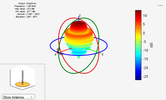
Pattern Behavior
Plot the directivity radiation pattern of the helical antenna at the center frequency of 1.65 GHz. This pattern confirms the axial mode of operation for the helical antenna.
figure
pattern(hx,fc);
To calculate the directivity variation of the main beam as a function of frequency, choose a frequency range according to [2].
Nf1 = 15;
Nf2 = 20;
fmin = 1.2e9;
fmax = 2.1e9;
fstep = 0.1e9;
fband1 = linspace(fmin,1.3e9,Nf1);
fband2 = linspace(fmin,fmax,Nf2);
freq = unique([fband1,fband2]);
Nf = length(freq);
D = nan(1,Nf);
f_eng = freq./1e9;
f_str = 'G';
fig1 = figure;
for i = 1:length(freq)
    D(i) = pattern(hx,freq(i),0,90);
    figure(fig1)
    plot(f_eng,D,'x-')
    grid on
    axis([f_eng(1) f_eng(end) 9 16 ])
    xlabel(["Frequency (" f_str "Hz)"])
    ylabel("Directivity (dBi)")
    title("Peak Directivity Variation vs. Frequency")
    drawnow
end

Discussion on the Results
Comparing this result with Fig. 11 in [2] replicated below, we establish the quantitative agreement.

Simulated and measured RHC gain for the NB and WB3 designs [2] (Reproduced with permission from IEEE)
References
[1] J. D. Kraus, "Helical Beam Antennas," Electronics, 20, April 1947, pp. 109-111.
[2] A. R. Djordjevic, A. G. Zajic, M. M. Ilic, G. L. Stuber, "Optimization of Helical antennas [Antenna Designer's Notebook]," IEEE Antennas and Propagation Magazine, vol.48, no.6, pp.107-115, Dec. 2006.
[3] C. A. Balanis, 'Antenna Theory. Analysis and Design,' p. 514, Wiley, New York, 3rd Edition, 2005.