Physical Optics Solver
Physical optics (PO) solver in Antenna Toolbox™ allows you to solve for the RCS of an object. In physical optics, the incident field is used to calculate the currents on the surface of the structure in response to the impinging plane wave. With the currents available, you can obtain the scattered field at desired points in the far-field.
Subdomain RWG Basis Functions and Extra Dimensions
The familiar Rao-Wilton-Glisson (RWG) basis functions on triangles are based on [2].
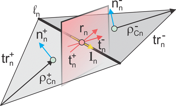
In the image, for two arbitrary triangular patches trn+ and trn- having areas An+ and An- and sharing a common edge ln the basis functions have the form
where is the vector drawn from the free vertex of the triangle trn+ to the observation point ; is the vector drawn from the observation point to the free vertex of the triangle trn-. The basis function is zero outside the two adjacent triangles. The RWG vector basis function is linear and has no flux (that is, has no normal component) through its boundary.
From [1], along with the standard definition, this method requires two unit normal vectors and two-unit vectors also shown in the figure. Vector is the plane of triangle trn+; both vectors are perpendicular to the edge ln. They are defined at the center of edge, which isln denoted by . Directions of
are also shown in the figure. This technique assumes that the normal vectors are properly (angle between adjacent must be less than 180 degrees) and uniquely defined. Specific vector orientation (e.g. outer or inner normal vectors) does not matter. We then form two cross product vectors ,
and establish that both such unit vectors directed along the edge are identical,
Only vector is eventually needed.
Finding IPO
The suitable PO approximation has the form:
where δ accounts for the shadowing effects. If the observation point lies in the shadowed region, δ must be zero. Otherwise it equals to ±1 depending on the direction of incidence with respect to the orientation of the normal vector . Using Eq.(4) yields:
Ref [3] outlines an elegant way to express unknowns explicitly, using an interesting variation of the collocation method. First, consider a collocation point that tends to the edge center of a center basis function and is located in the plus triangle. Multiply Eq.(6) by vector . Since the normal component of the basis function at the edge is one and all the other basis functions sharing the same triangle have no normal component at the edge, the result becomes
Repeat the same operation with minus triangle:
Add equations 7(a) and 7(b), divide the result by two, and transform the triple vector product to obtain:
Therefore, according to equations (2) and (3),
Determination of Illuminated or Shadow Regions
The calculation of needs to account for the effect of shadowing. For simple convex structures the use of the normal to test against the direction of the radiation would indicate the illuminated or shadow region. If the normal of the triangle is pointing in the opposite direction of the radiation, then the face is illuminated. If the normal of the triangle is in the same direction, then the face is shadowed. But this simple test fails when the object is nonconvex as is the case in more complex structures. To handle this, perform a segment-triangle intersection test to rigorously determine the value of . The value of is 0 for shadow faces or ±1 depending on the direction of incidence with respect to the orientation of normal vector. To implement this relative to the RWG basis functions that are formed on the surface of the PO region, check for both arbitrary triangular patches and to be in the illuminated region and only then consider the contribution made by the edge to the calculation of the PO current. If either triangle is in the shadow region, the delta value is evaluated to zero and therefore the edge does not contribute.
Note
The classic physical optics (PO) formulation does not support multiple reflections from a physical structure illuminated by a plane wave. The PO current density is valid only in the illuminated region of the structure. This formulation does not handle any reflections from the illuminated region that result in secondary illumination of a different region of the structure.
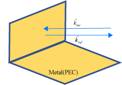
Case 1: When the direction of the incident plane wave results in a reflection back in the direction of the incoming source.
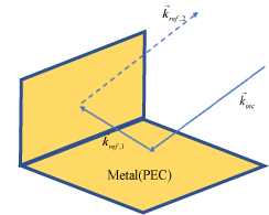
Case 2: When the angle of the incident plane wave causes a second reflection from a different part of the structure, this reflection contributes significantly to the scattered field and is not considered by the PO solver.
.
References
[1] U. Jakobus and F. M. Landstorfer, “Improved PO-MM Formulation for Scattering from Three-Dimensional Perfectly Conducting Bodies of Arbitrary Shape,” IEEE Trans. Antennas and Propagation, vol. AP-43, no. 2, pp. 162-169, Feb. 1995.
[2] S. M. Rao, D. R. Wilton, and A. W. Glisson, “Electromagnetic scattering by surfaces of arbitrary shape,” IEEE Trans. Antennas and Propagation, vol. AP-30, no. 3, pp. 409-418, May 1982.
[3] S. Makarov, Antenna and EM Modeling in MATLAB, Wiley, New York, 2002.