PM Modulator Passband
Modulate using phase modulation
Libraries:
Communications Toolbox /
Modulation /
Analog Passband Modulation
Description
The PM Modulator Passband block modulates a signal using phase modulation. The output is a passband representation of the modulated signal. The frequency of the output signal varies with the amplitude of the input signal. Both the input and output signals are real scalar signals.
Examples
Sample a 100 Hz linear frequency sweep chirp with a 400 Hz target frequency at 4 kilosamples per second. Modulate the input signal using the phas modulation method. Demodulate the signal. Plot the input signal, the modulated signal, and the demodulated signal.
The pmmoddemod_passband model modulates the input linear frequency sweep chirp signal using the PM method at a carrier frequency of 1.5 kHz with pi/2 phase deviation and then demodulates the signal. When the model runs, it plots the signals. This configuration ensures the Hilbert transform filter operates in the flat section of the magnitude response and that the demodulated signal has the desired magnitude and form.
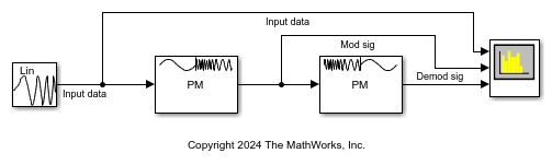
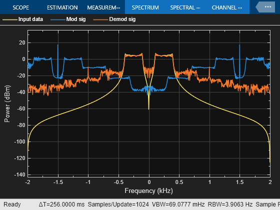
The spectrum analyzer plot shows input signal, the modulated signal, and the demodulated signal.
Limitations
This block does not work inside a triggered subsystem.
Ports
Input
Output
Parameters
Block Characteristics
Data Types |
|
Multidimensional Signals |
|
Variable-Size Signals |
|
Algorithms
The PM Modulator Passband block uses phase modulation to encode a message signal as variations in the instantaneous phase of a carrier wave. The PM Modulator Passband block modulates using phase modulation to f.
For an input signal u(t), as a function of time t, the output signal is
where:
fc represents the Carrier frequency (Hz) parameter.
θ represents the Initial phase (rad) parameter.
Kc represents the Phase deviation (rad) parameter.
Extended Capabilities
Version History
Introduced before R2006a