Generate HDL Code for Viterbi Decoder
This example shows two different modeling patterns to implement the Viterbi decoding algorithm and generate HDL code. One of the patterns uses a MATLAB Function block. The other pattern uses the Viterbi Decoder block. You need a Communications Toolbox license to use the Viterbi Decoder block.
Model Algorithm with Viterbi Decoder Block
The model hdlcoder_commviterbi demonstrates how to generate code for a model that contains a fixed-point Viterbi Decoder block used in soft decision convolutional decoding. To learn more about HDL support for the Viterbi Decoder block see the HDL Code Generation section of the block page in documentation.
To open the model, run this command in the MATLAB Command Window:
open_system('hdlcoder_commviterbi');
In this model, the top-level subsystem Viterbi Decoder Subsystem contains a Viterbi Decoder block. To open this subsystem, run these commands:
subsystem = 'hdlcoder_commviterbi/Viterbi Decoder Subsystem';
open_system(subsystem);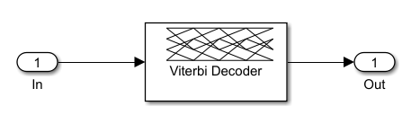
The Viterbi Decoding Algorithm
There are three main units in the Viterbi decoding algorithm, the branch metric computation (BMC), add-compare-select (ACS), and traceback decoding. This diagram illustrates the three units in the algorithm:

The Renormalization Method
The Viterbi decoding algorithm prevents the overflow of the state metrics in the ACS component by subtracting the minimum value of the state metrics at each time step, as shown in this figure:

Obtaining the minimum value of all the state metric elements in one clock cycle results in a poor clock frequency for the circuit. You can improve the performance of the circuit by adding pipeline registers. However, subtracting the minimum value delayed by the pipeline registers from the state metrics may still lead to overflow. The hardware architecture modifies the renormalization method and avoids the state metric overflow in three steps:
The architecture calculates values for the threshold and step parameters based on the trellis structure and the number of soft decision bits.
The architecture compares the delayed minimum value to the threshold.
If the minimum value is greater than or equal to the threshold value, the implementation subtracts the step value from the state metric. Otherwise, it performs no adjustment.
This figure illustrates the modified renormalization method:

Optimal State Metric Word Length Calculation
The hardware implementation calculates the optimal word length of the state metric and compares it with the value you specify for the State metric word length parameter in the Viterbi Decoder block. The hardware architecture uses the optimal value if it is smaller than the one you specify. During code generation, HDL Coder displays a message to show the value in the Diagnostic Viewer. If the calculated value is larger than the value you specify, HDL Coder reports an error message and displays the optimal value.
Applying the calculated optimal state metric word length in the hardware implementation may significantly reduce the hardware resource if the value you specify is too large. For example, if you set 16 bits as the State metric word length but only 9 bits are required to achieve the same numerical results, applying the calculated optimal state metric word length in the hardware architecture saves approximately 40% of the register resources. The calculated optimal state metric word length for some typical trellises is displayed in this table:

This model decodes a convolutional code with a decoder rate of 1/2, constraint length of 7, and (171,133) encoding. It uses 3-bit soft decision decoding. The decoder runs at continuous mode with a traceback depth of 32. The state metric word length is 16 bits.
To validate the parameter settings of the Viterbi Decoder block, run these commands:
workingdir = tempname;
checkhdl(subsystem,'TargetDirectory',workingdir);
### Running HDL checks on the model 'hdlcoder_commviterbi'. ### Begin compilation of the model 'hdlcoder_commviterbi'... ### Creating HDL Code Generation Check Report Viterbi_Decoder_Subsystem_report.html ### HDL check for 'hdlcoder_commviterbi' complete with 0 errors, 0 warnings, and 5 messages.
Running checkhdl generates messages that report:
The default value of TracebackStagesPerPipeline HDL block property
The state metric word length used in the HDL code compared with the one set for State metric word length parameter on the Viterbi Decoder block
The total delay introduced by the pipeline registers with respect to the Viterbi Decoder block
To generate HDL for the subsystem that contains the Viterbi Decoder block, run this command:
makehdl(subsystem,'TargetDirectory',workingdir);### Working on the model hdlcoder_commviterbi ### Generating HDL for hdlcoder_commviterbi/Viterbi Decoder Subsystem ### Using the config set for model hdlcoder_commviterbi for HDL code generation parameters. ### Running HDL checks on the model 'hdlcoder_commviterbi'. ### Begin compilation of the model 'hdlcoder_commviterbi'... ### Working on the model 'hdlcoder_commviterbi'... ### The code generation and optimization options you have chosen have introduced additional pipeline delays. ### The delay balancing feature has automatically inserted matching delays for compensation. ### The DUT requires an initial pipeline setup latency. Each output port experiences these additional delays. ### Output port 1: 20 cycles. ### Working on... GenerateModel ### Begin model generation 'gm_hdlcoder_commviterbi'... ### Rendering DUT with optimization related changes (IO, Area, Pipelining)... ### Model generation complete. ### Generated model saved at /tmp/Bdoc26a_3233028_997287/tp7575d4a9_97f6_47ba_b30a_26a5fdd97975/hdlcoder_commviterbi/gm_hdlcoder_commviterbi.slx ### Begin VHDL Code Generation for 'hdlcoder_commviterbi'. ### Working on hdlcoder_commviterbi/Viterbi Decoder Subsystem/Viterbi Decoder/BranchMetric as /tmp/Bdoc26a_3233028_997287/tp7575d4a9_97f6_47ba_b30a_26a5fdd97975/hdlcoder_commviterbi/BranchMetric.vhd. ### Working on hdlcoder_commviterbi/Viterbi Decoder Subsystem/Viterbi Decoder/ACS/ACSEngine/ACSUnit as /tmp/Bdoc26a_3233028_997287/tp7575d4a9_97f6_47ba_b30a_26a5fdd97975/hdlcoder_commviterbi/ACSUnit.vhd. ### Working on hdlcoder_commviterbi/Viterbi Decoder Subsystem/Viterbi Decoder/ACS/ACSEngine as /tmp/Bdoc26a_3233028_997287/tp7575d4a9_97f6_47ba_b30a_26a5fdd97975/hdlcoder_commviterbi/ACSEngine.vhd. ### Working on hdlcoder_commviterbi/Viterbi Decoder Subsystem/Viterbi Decoder/ACS/ACSRenorm as /tmp/Bdoc26a_3233028_997287/tp7575d4a9_97f6_47ba_b30a_26a5fdd97975/hdlcoder_commviterbi/ACSRenorm.vhd. ### Working on hdlcoder_commviterbi/Viterbi Decoder Subsystem/Viterbi Decoder/ACS as /tmp/Bdoc26a_3233028_997287/tp7575d4a9_97f6_47ba_b30a_26a5fdd97975/hdlcoder_commviterbi/ACS.vhd. ### Working on hdlcoder_commviterbi/Viterbi Decoder Subsystem/Viterbi Decoder/Traceback/TracebackUnit as /tmp/Bdoc26a_3233028_997287/tp7575d4a9_97f6_47ba_b30a_26a5fdd97975/hdlcoder_commviterbi/TracebackUnit.vhd. ### Working on hdlcoder_commviterbi/Viterbi Decoder Subsystem/Viterbi Decoder/Traceback as /tmp/Bdoc26a_3233028_997287/tp7575d4a9_97f6_47ba_b30a_26a5fdd97975/hdlcoder_commviterbi/Traceback.vhd. ### Working on hdlcoder_commviterbi/Viterbi Decoder Subsystem/Viterbi Decoder as /tmp/Bdoc26a_3233028_997287/tp7575d4a9_97f6_47ba_b30a_26a5fdd97975/hdlcoder_commviterbi/Viterbi_Decoder.vhd. ### Working on hdlcoder_commviterbi/Viterbi Decoder Subsystem as /tmp/Bdoc26a_3233028_997287/tp7575d4a9_97f6_47ba_b30a_26a5fdd97975/hdlcoder_commviterbi/Viterbi_Decoder_Subsystem.vhd. ### Generating package file /tmp/Bdoc26a_3233028_997287/tp7575d4a9_97f6_47ba_b30a_26a5fdd97975/hdlcoder_commviterbi/Viterbi_Decoder_Subsystem_pkg.vhd. ### Code Generation for 'hdlcoder_commviterbi' completed. ### Generating HTML files for code generation report at index.html ### Creating HDL Code Generation Check Report Viterbi_Decoder_Subsystem_report.html ### HDL check for 'hdlcoder_commviterbi' complete with 0 errors, 0 warnings, and 5 messages. ### HDL code generation complete.
The top-level VHDL file name matches the name of the block in the model. The Viterbi_Decoder unit generated in the Viterbi_Decoder.vhd file contains three units: BranchMetric, ACS, and Traceback. The ACS and Traceback units instantiate the ACSUnit and TracebackUnit units multiple times, respectively. The package file Viterbi_Decoder_Subsystem_pkg.vhd includes the data type definitions.
To generate a test bench for the subsystem that contains the Viterbi Decoder block, run this command:
makehdltb(subsystem,'TargetDirectory',workingdir);### Begin TestBench generation. ### Generating HDL TestBench for 'hdlcoder_commviterbi/Viterbi Decoder Subsystem'. ### Begin compilation of the model 'hdlcoder_commviterbi'... ### Begin compilation of the model 'gm_hdlcoder_commviterbi'... ### Begin simulation of the model 'gm_hdlcoder_commviterbi'... ### Collecting data... ### Generating test bench data file: In_rsvd.dat. ### Generating test bench data file: Out_rsvd_expected.dat. ### Working on Viterbi_Decoder_Subsystem_tb as /tmp/Bdoc26a_3233028_997287/tp7575d4a9_97f6_47ba_b30a_26a5fdd97975/hdlcoder_commviterbi/Viterbi_Decoder_Subsystem_tb.vhd. ### Generating package file /tmp/Bdoc26a_3233028_997287/tp7575d4a9_97f6_47ba_b30a_26a5fdd97975/hdlcoder_commviterbi/Viterbi_Decoder_Subsystem_tb_pkg.vhd. ### HDL TestBench generation complete.
Optimize Traceback Unit
You can optimize the Traceback unit that HDL Coder generates in the Viterbi_Decoder.vhd file by either pipelining the register-based traceback unit or using the RAM-based traceback architecture.
Register-Based Traceback Pipelining
The Viterbi Decoder block decodes every bit by tracing through a traceback depth you define as the TracebackStagesPerPipeline property. Because the block implements a complete traceback for each decision bit, HDL Coder uses registers to store the minimum state index and branch decision in the Traceback unit. You can improve the performance of the generated circuit by pipelining this unit. Add pipeline registers to the Traceback unit by specifying the number of traceback stages for each pipeline registers. To add pipeline registers, right-click the Viterbi Decoder block and click HDL Code > HDL Block Properties. Set the TracebackStagesPerPipeline to 4.

This setting results in the insertion of a pipeline register for every four traceback units in the model, as illustrated in this figure:

The TracebackStagesPerPipeline property balances the circuit performance based on system requirements. A smaller property value adds more registers and increases the speed of the traceback circuit. Increasing the number results in a lower number of registers and a decrease in the circuit speed.
In this example, adjusting the TracebackStagesPerPipeline property from 4 to 8 reduces the pipeline register usage in half and changes the circuit speed from 173MHz to 94 MHz.
RAM-Based Traceback Pipelining
Instead of using registers, you can use RAMs to save the survivor branch information. Right-click the Viterbi Decoder block and click HDL Code > HDL Block Properties. Set Architecture to RAM-based Traceback.

There are two differences between the register-based and the RAM-based traceback architectures:
The register-based implementation combines the traceback and decode operations into one step and uses the best state found from the minimum operation as the decoding initial state. The RAM-based implementation traces back through one set of data to find the initial state to decode the previous set of data.
The register-based implementation decodes one bit after a complete trace back. The RAM-based implementation traces back through M samples, decodes the previous M bits in reverse order, and releases one bit in order at each clock cycle.
Due to the differences in the two traceback algorithms, the RAM-based implementation produces different numerical results than the register-based traceback. A longer traceback depth, for example, 10 times of constraint length, is recommended in the RAM-based traceback to achieve a similar bit error rate (BER) as the register-based implementation.
The size of RAM required for the implementation depends on the trellis and the traceback depth. This table summarizes the RAM usage for some typical trellis structures.

In this example, the RAM-based traceback unit uses 90% fewer registers than the register-based traceback unit with pipelining every 4 stages by using similar clock constraints in synthesis. The two implementations provide a register-RAM tradeoff you can tailor to the individual design.
Model Algorithm with MATLAB Function Block
The model hdlcoderviterbi2 demonstrates an implementation of a Viterbi decoder that incorporates MATLAB Function blocks for use in simulation and HDL code generation.
To open the model, run this command:
open_system('hdlcoderviterbi2');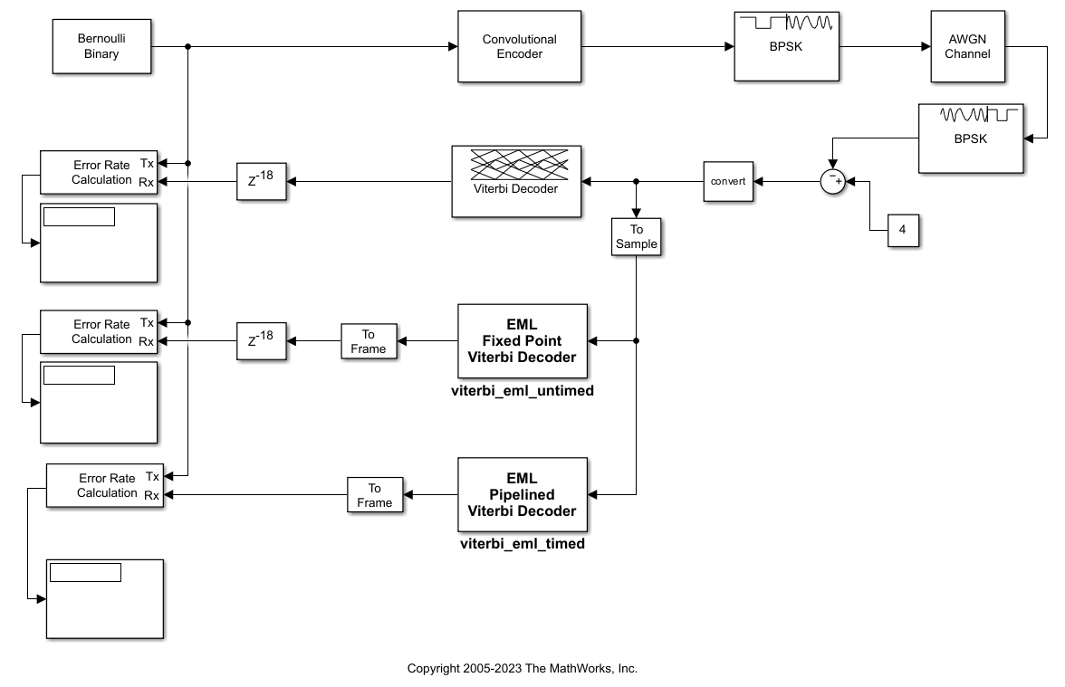
When your design contains MATLAB Function blocks, run the Check for MATLAB Function block settings (HDL Coder) check in the HDL Code Advisor before you generate HDL code. This check verifies whether you use the recommended MATLAB Function block settings for HDL code generation.
Alternately, run this command:
checkhdl('hdlcoderviterbi2/viterbi_eml_timed')### Running HDL checks on the model 'hdlcoderviterbi2'. ### Begin compilation of the model 'hdlcoderviterbi2'... ### Creating HDL Code Generation Check Report viterbi_eml_timed_report.html ### HDL check for 'hdlcoderviterbi2' complete with 0 errors, 0 warnings, and 0 messages.
To simulate the model, in the Simulink Toolstrip, on the Simulation tab, click Run.
Alternately, run this command:
sim('hdlcoderviterbi2');To generate HDL for the viterbi_eml_timed subsystem, open the HDL Coder app. Select the viterbi_eml_timed in your model. In the HDL Code tab, ensure that Code for is set to viterbi_eml_timed. To remember the selection, click the pin button ![]() to pin the subsystem
to pin the subsystem viterbi_eml_timed. Click Generate HDL Code.
Alternately, run this command:
makehdl('hdlcoderviterbi2/viterbi_eml_timed');### Working on the model hdlcoderviterbi2 ### Generating HDL for hdlcoderviterbi2/viterbi_eml_timed ### Using the config set for model hdlcoderviterbi2 for HDL code generation parameters. ### Running HDL checks on the model 'hdlcoderviterbi2'. ### Begin compilation of the model 'hdlcoderviterbi2'... ### Working on the model 'hdlcoderviterbi2'... ### Working on... GenerateModel ### Begin model generation 'gm_hdlcoderviterbi2'... ### Copying DUT to the generated model.... ### Model generation complete. ### Generated model saved at hdlsrc/hdlcoderviterbi2/gm_hdlcoderviterbi2.slx ### Begin VHDL Code Generation for 'hdlcoderviterbi2'. ### Working on hdlcoderviterbi2/viterbi_eml_timed/ACS Unit/ACS as hdlsrc/hdlcoderviterbi2/ACS.vhd. ### Working on hdlcoderviterbi2/viterbi_eml_timed/ACS Unit/Renormalize_pipelined as hdlsrc/hdlcoderviterbi2/Renormalize_pipelined.vhd. ### Working on hdlcoderviterbi2/viterbi_eml_timed/ACS Unit as hdlsrc/hdlcoderviterbi2/ACS_Unit.vhd. ### Working on hdlcoderviterbi2/viterbi_eml_timed/TraceBack Unit/TBU1 as hdlsrc/hdlcoderviterbi2/TBU1.vhd. ### Working on hdlcoderviterbi2/viterbi_eml_timed/TraceBack Unit/TBU_OUT as hdlsrc/hdlcoderviterbi2/TBU_OUT.vhd. ### Working on hdlcoderviterbi2/viterbi_eml_timed/TraceBack Unit as hdlsrc/hdlcoderviterbi2/TraceBack_Unit.vhd. ### Working on hdlcoderviterbi2/viterbi_eml_timed/BMU as hdlsrc/hdlcoderviterbi2/BMU.vhd. ### Working on hdlcoderviterbi2/viterbi_eml_timed as hdlsrc/hdlcoderviterbi2/viterbi_eml_timed.vhd. ### Generating package file hdlsrc/hdlcoderviterbi2/viterbi_eml_timed_pkg.vhd. ### Code Generation for 'hdlcoderviterbi2' completed. ### Generating HTML files for code generation report at index.html ### Creating HDL Code Generation Check Report viterbi_eml_timed_report.html ### HDL check for 'hdlcoderviterbi2' complete with 0 errors, 0 warnings, and 0 messages. ### HDL code generation complete.
To generate a test bench for the viterbi_eml_timed subsystem, on the HDL Code tab, click Generate Testbench.
Alternately, run this command:
makehdltb('hdlcoderviterbi2/viterbi_eml_timed');### Begin TestBench generation. ### Generating HDL TestBench for 'hdlcoderviterbi2/viterbi_eml_timed'. ### Begin compilation of the model 'hdlcoderviterbi2'... ### Begin compilation of the model 'gm_hdlcoderviterbi2'... ### Begin simulation of the model 'gm_hdlcoderviterbi2'... ### Collecting data... ### Generating test bench data file: hdlsrc/hdlcoderviterbi2/In1.dat. ### Generating test bench data file: hdlsrc/hdlcoderviterbi2/Out1_expected.dat. ### Working on viterbi_eml_timed_tb as hdlsrc/hdlcoderviterbi2/viterbi_eml_timed_tb.vhd. ### Generating package file hdlsrc/hdlcoderviterbi2/viterbi_eml_timed_tb_pkg.vhd. ### HDL TestBench generation complete.
References
Clark, George C., and J. Bibb Cain. Error-Correction Coding for Digital Communications. Springer US, 1981.
Feygin, G., and P. Gulak. “Architectural Tradeoffs for Survivor Sequence Memory Management in Viterbi Decoders.” IEEE Transactions on Communications, vol. 41, no. 3, Mar. 1993, pp. 425–29.