Overview of Driving Simulation Test Bench
Driving Simulation Test Bench is a Simulink® model that enables you to test various automated driving applications, such as
autonomous emergency braking (AEB) and lane keep assist (LKA) scenarios. The test bench model
enables you to integrate the sensor and scenario interfaces with your controller and test the
scenario with a high-fidelity vehicle dynamics model. The test bench model also enables you to
simulate and test a custom vehicle model in the scenario.
The test bench contains interfaces for integrating RoadRunner Scenario with MATLAB®, enabling you to test your custom scenarios. Additionally, the test bench supports simulation and testing of various Euro NCAP® scenarios, and enables you to generate Euro NCAP test reports.
Prerequisites
To simulate and test scenarios using the driving simulation test bench, you must have these products licensed and installed:
Simulink — Run the driving simulation test bench Simulink model.
Simulink Test™ — Automate simulation of the driving simulation test bench Simulink model on scenario variants.
Automated Driving Toolbox™ — Use driving scenarios.
Automated Driving Toolbox Test Suite for Euro NCAP® Protocols support package — Generate, test, and create test reports for Euro NCAP test scenarios.
RoadRunner — Import test scenarios for cosimulation.
RoadRunner Scenario — Simulate imported test scenarios.
Additionally, these products enable you to extend the functionality of the driving simulation test bench:
RoadRunner Asset Library Add-On (optional) — Map actor assets between driving scenarios and RoadRunner scenarios.
Vehicle Dynamics Blockset™ (optional) — Use the 14DOF vehicle dynamics for obtaining vehicle simulation information.
Model Predictive Control Toolbox™ (optional) — Use Lane Support System (LSS) scenarios in the driving simulation test bench.
Test Bench Components
To get started with the test bench components, open and examine the driving simulation test bench model.
To run a driving simulation test bench, you must set up and configure a test bench project. For more information, see Set Up and Configure Test Bench.
Navigate to the directory in which you want to create a driving simulation test bench
project, and a driving simulation test bench project by using the
startDrivingProject
function.
startDrivingProject(pwd)
Create a test bench configuration object by using the
configureDrivingTestBench
object.
drivingConfigObj = configureDrivingTestBench;
Configure the test bench model by using the setup object function of the
configureDrivingTestBench
object.
setup(drivingConfigObj)
Alternatively, you can open the AEB Test Bench for Euro NCAP Scenarios example.
The TestBench folder in the project directory contains a
DrivingTestBench.slx
Simulink file, which you can use to simulate and test the performance of the test
controller. Open the test bench model.
modelName  = "DrivingTestBench";
open_system(modelName)

The driving simulation test bench model contains these modules:
Controller— Controls the steering angle and acceleration of the ego vehicle. A reference model that integratesController.slxinto theDrivingTestBench.slxmodel.Vehicle Dynamics— Specifies the ego vehicle dynamics. TheVehicle Dynamicssubsystem consists of a variant subsystem that has two vehicle variants, 3DOF (default) and 14DOF.Scenario and Environment— Specifies vehicle path, sensor blocks, and RoadRunner Scenario blocks, which configure, read from, and write to RoadRunner Scenario.
Controller
The Controller reference model accepts inputs such as velocity, actor
pose, tracks, and lane detections from the Scenario and Environment
subsystem. It computes the steering angle and acceleration of the ego vehicle, and provides
them as outputs to the Vehicle Dynamics subsystem.
Open the Controller reference
model.
open_system("Controller")
The controller contains these modules:
AEB Controller— TheAEB Controllersubsystem inputs theTracksandEgo Velocitysignals from theSensors and Environmentsubsystem. The controller finds the most important object (MIO) using theTracksinput and enables theAEB Brake Statusif there is chance of collision with the MIO.LKA Controller— TheLKA Controllersubsystem inputs signals from theSensors and Environmentsubsystem such asVelocity,Lane Bus, andSteer Feedback. This controller enables the ego vehicle to follow the input trajectory and accelerates the ego with the input velocity.Trajectory Following Controller— TheTrajectory Following Controllersubsystem inputs signals from theSensors and Environmentsubsystem such asSet Velocity,Curvature Sequence, andEgo Pose. This controller also enables the ego vehicle to follow the input trajectory and accelerates the ego with the input velocity.Controller Mode Selector— If theAEB EnableandAEB Brake Statussignals aretrue, this subsystem accepts theAEB Decelerationsignal from theAEB Controlleras input. Otherwise, based on thelka_test_enablesignal status, this subsystem accepts theCruise AccelerationandCruise Steer Controlsignals, received from either theLKA Controlleror theTrajectory Following Controller. This subsystem outputs theAcceleration CmdandSteering Angleto control the vehicle dynamics.
To configure the controller for the test bench model, you can use the
setup object function of the configureDrivingTestBench
object. For
example,
setup(drivingConfigObj,Controller="AEB")
You can swap the controller reference models with any ADAS controller under test that
can leverage the interface signals. The input interface to the controller reference model
has signals that contains the data from the scenario, vehicle, and sensors. Use the bus
selector block to see the list of available signals after the Inputs
port. You can select one or more of these signals that suit your controller under test:
aeb_test_enable— Enables the AEB test when there is a collision between the target vehicle and the ego vehicle in the input scenario.lka_test_enable— Enables the LKA test when the ego vehicle is out of the lane in which it is traveling.BusRefPathInfo— Contains reference ego path information such asCurvatureDeviation,LateralDeviation,RelativeYawAngle, andref_pose.BusActorPose— Contains ego actor information such asActorID,Position,Velocity,Roll,Pitch,Yaw, andAngularVelocity.BusMultiObjectTracker1— Contains multi-object tracking information such as number of tracks, track IDs, and age of the tracks.set_velocity— Sets the velocity of the ego vehicle as the velocity specified in the RoadRunner Scenario.BusVision— Contains object detection and lane information from the visual measurements in the RoadRunner Scenario.LaneBus— Contains lane detection information such as lane boundary points, number of lane boundaries, sensor index, and lane detection timestamps.

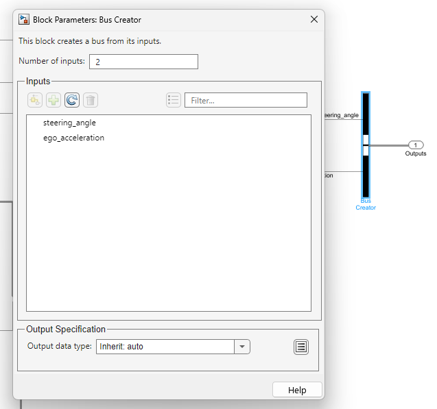
The output interface has these signals:
steering_angle— Specifies the steering angle of the ego vehicle. Units are in degrees.ego_acceleration— Specifies the acceleration of the ego vehicle. Units are in meters per second squared.
Vehicle Dynamics
The Vehicle Dynamics subsystem incorporates two distinct vehicle
models, 3DOF and 14DOF, to dynamically update the state of the ego vehicle based on the
inputs from the Controller reference model.
Open the Vehicle Dynamics
subsystem.
open_system(modelName + "/Vehicle Dynamics/Vehicle Dynamics")

The 3DOF bicycle model block implements a rigid two-axle single-track
vehicle body model to calculate longitudinal, lateral, and yaw motion. The block also
calculates the body mass, aerodynamic drag, and weight distribution between the axles due to
acceleration and steering. For more information, see the Bicycle Model
block.
Open the 3DOF reference
model.
open_system(modelName + "/Vehicle Dynamics/Vehicle Dynamics/3DOF")
To configure the vehicle dynamics of the test bench model you can use the
setup object function of the configureDrivingTestBench
object. For
example,
vehicle = struct('Mass',1575,'YawMomentOfInertia',2875,'FrontTireCorneringStiffness',19000, ...
                    'RearTireCorneringStiffness',33000,'Fidelity',"3DOF",'StartFromRest',true);
setup(drivingConfigObj,Vehicle=vehicle)
Compared to the 3DOF variant, the 14DOF variant
offers additional simulation aspects such as transmission dynamics, tire interactions, load
shifting, braking behavior, and the vehicle powertrain response. For more information on
vehicle dynamics models, see Passenger Vehicle Dynamics Models (Vehicle Dynamics Blockset).
Open the 14DOF reference
model.
open_system("VehDyn14DOF")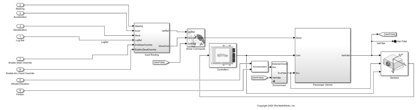
Scenario and
          Environment
The Scenario and Environment subsystem configures vehicle paths,
sensor blocks, and RoadRunner Scenario blocks, which are essential for scenario setup and execution.
Open the Scenario and Environment
subsystem.
open_system(modelName + "/Scenario and Environment")

The Scenario and Environment subsystem contains these modules:
RoadRunner Scenario— ARoadRunner Scenario block that defines the interface for an actor model.Path Action Reader— RoadRunner Scenario Reader block that reads the reference path of the ego vehicle.Self Actor Runtime Reader— RoadRunner Scenario Reader block that reads the ego actor runtime information.All Actor Runtime— RoadRunner Scenario Reader block that reads the runtime information of all actors in the scenario.Self Actor Runtime Writer— RoadRunner Scenario Writer block that writes the ego vehicle runtime to RoadRunner Scenario.Ego Path— Subsystem that reads the reference path and current ego pose and computes the reference curvature, lateral deviation, relative angle, and reference pose required for the test controller.Sensors— Variant subsystem that enables ground truth or probabilistic vision and radar sensors.Test Enable— Subsystem that provides theAEB Test Enablesignal andStop Simulationsignal by using theTest Start Positioncomputed by thesetupobject function of theconfigureDrivingTestBenchobject.
Note: For your custom controller
requirements, you can extract additional signals from the Scenario and
Environment subsystem and input them into the Controller
reference model.
MATLAB and RoadRunner Scenario Cosimulation
You can integrate the driving simulation test bench model with a RoadRunner scenario that has been configured with path following mode, by default. This
example demonstrates cosimulation between the DrivingTestBench
Simulink model and a Euro NCAP Car-to-Car Rear stationary (CCRs) RoadRunner scenario. For more information on the CCRs scenario, see Euro NCAP Test Scenarios for Protocol Specification Years 2023–2025.
To set up the DrivingTestBench model with the CCRs RoadRunner scenario, you must first initialize the RoadRunner application, open the scenario, and establish a connection with MATLAB. For instructions on creating this connection, see Simulate RoadRunner Scenarios with Actors Modeled in Simulink.
Start the RoadRunner application interactively by using the roadrunnerSetup
function. The function opens a dialog box in which you specify the project folder and
installation folder to use when opening RoadRunner. The function returns a roadrunner object,
rrApp, that enables you to perform common tasks in the RoadRunner application, such as opening, closing, and saving scenes and projects. Because
this example uses assets from the RoadRunner Asset Library add-on, you must use a RoadRunner Project created with Base + Add On assets
selected.
rrApp = roadrunnerSetup;
Copy the CCRs scenario file to the RoadRunner project and open the scenario in RoadRunner. For more information on how to copy the scenario, see the AEB Test Bench for Euro NCAP Scenarios example.
openScenario(rrApp,CCRsFileName)

After opening the scenario, you must associate an actor behavior with the
DrivingTestBench Simulink model. For information on how to associate
actor behavior in RoadRunner Scenario, see Associate Actor Behavior in RoadRunner and Simulate Scenario.

After associating the behavior, establish the connection between RoadRunner Scenario and MATLAB.
Connect to the RoadRunner Scenario server for cosimulation by using the createSimulation
function. Enable data logging, turn off simulation pacing for best simulation performance, set
the simulation end time, and set the RoadRunner Scenario simulation step size for your test
bench model.
rrSim = createSimulation(rrApp);
set(rrSim,Logging="on")
set(rrSim,PacerStatus="Off")
set(rrSim,MaxSimulationTime=30)
set(rrSim,StepSize=0.03)
Configure and set up the driving test bench for continuous integration of MATLAB with the RoadRunner scenario.
drivingConfigObj  = configureDrivingTestBench;
setup(drivingConfigObj)
Simulate the driving test bench model, and fetch the simulation log for further analysis.
set(rrSim,SimulationCommand="Start")
while strcmp(get(rrSim,"SimulationStatus"),"Running")
    pause(1)
end
simulationLog = get(rrSim,"SimulationLog");
Note: You must run the setup function
every time you modify the scenario to ensure that the base workspace and the model workspace
variables have been updated with the latest values used by the test bench.
Once the simulation is complete, close RoadRunner Scenario.
close(rrApp)
Further Exploration
DrivingTestBench is a comprehensive test bench model for testing
automated driving (AD) and advanced driver assistance systems (ADAS) controllers across a
variety of scenarios including Euro NCAP test scenarios.
For more information on how to configure and simulate a Euro NCAP scenario using DrivingTestBench, see the AEB Test Bench for Euro NCAP Scenarios and Euro NCAP Testing with RoadRunner Scenario examples.
See Also
Functions
roadrunnerSetup|createSimulation|openScenario|ScenarioSimulation|get|set|euroAssessment|assessmentTable|ncapScore|ncapReport|exportReport