Path Planning Using 3D Lidar Map
This example shows how to plan the reference path for navigation of an autonomous vehicle using a normal distribution transform (NDT) map. In this example, you use a prebuilt map of a parking lot scene in the Unreal Engine® simulation environment to plan a path on an NDT map with a Hybrid A* path planner.
Overview
A path-planning algorithm enables an autonomous vehicle to find the shortest obstacle-free path between a start location and a goal location. Path planning requires a map of the environment as well as the start and goal poses of the vehicle. This example shows a path-planning workflow on an NDT map that uses these steps:
Load and preprocess a prebuilt point cloud map.
Create an NDT map.
Build the vehicle cost map from the NDT map.
Set up a Hybrid A* planner.
Plan the path between the given start and goal poses.
Load and Preprocess Prebuilt Point Cloud Map
Load the prebuilt map of a parking lot scene.
load("parkingLotPCMapPoints.mat")Remove points above the vehicle and denoise the point cloud.
overVehiclePoints = ptCloudMapPoints(:,3) > 5;
ptCloudMapPoints(overVehiclePoints,:) = [];
denoisedPointCloud = pcdenoise(pointCloud(ptCloudMapPoints),NumNeighbors=20);
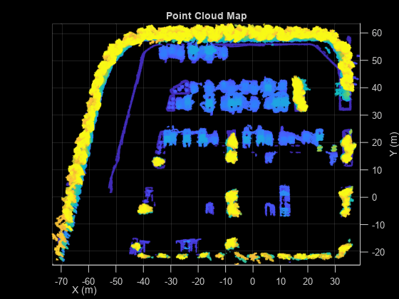
Visualize the preprocessed point cloud map.
figure
pcshow(denoisedPointCloud)
view(2)
title("Point Cloud Map")
xlabel("X (m)")
ylabel("Y (m)")
Create NDT Map
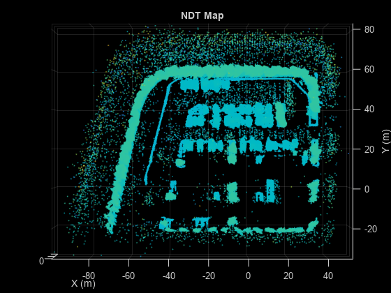
An NDT map is a compressed, memory-efficient representation of the point cloud suitable for localization. The object converts the point cloud map into a set of voxels (3D boxes), each represented by a 3D normal distribution. Create an NDT map from your preprocessed point cloud map by using the pcmapndt function.
voxelSize = 1;
ndtMap = pcmapndt(denoisedPointCloud,voxelSize);
Visualize the NDT map.
figure
show(ndtMap)
view(2)
title("NDT Map")
xlabel("X (m)")
ylabel("Y (m)")
Build Vehicle Costmap from NDT Map
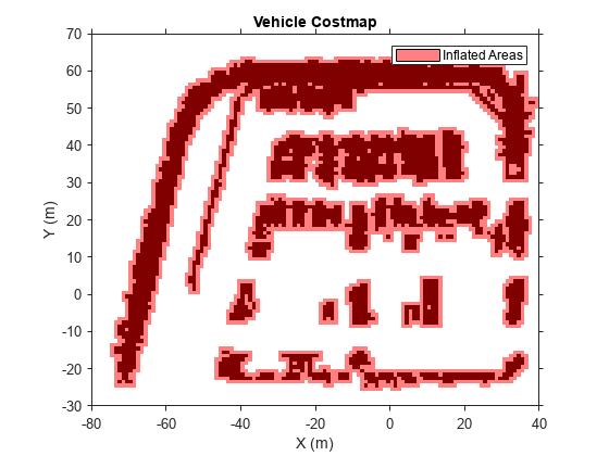
A costmap represents the planning search space around a vehicle. It contains environmental information such as obstacles or areas that the vehicle cannot traverse. In this example, you create the costmap using the mean points of the NDT map.
Get the mean points of the NDT map.
pts = ndtMap.VoxelMean;
Create a costmap using the vehicleCostmap function.
% Length and width of costmap in meters.
mapWidth = 120;
mapLength = 100;
% Set the cost value for empty space to zero.
costVal = 0;
% Side length of each square cell
cellSize = 1;

costmap = vehicleCostmap(mapWidth,mapLength,costVal,CellSize=cellSize,MapLocation=[-80 -30]);
To check for collisions, the costmap inflates obstacles using the inflation radius specified in its CollisionChecker property. Set the inflation radius to 0.25 meters.
costmap.CollisionChecker.InflationRadius = 0.25;
Add the mean points to the costmap, and set the cost of each mean point to 1.
xyPoint = round([pts(:,1),pts(:,2)]);
costVal = 1;
setCosts(costmap,xyPoint,costVal)
Visualize the costmap.
figure
plot(costmap)
title("Vehicle Costmap")
xlabel("X (m)")
ylabel("Y (m)")
Set Up Hybrid A* Path Planner
For path planning, use the Hybrid A* path planning algorithm, which generates a smooth path in a given 2D space for vehicles with nonholonomic constraints. For state validation, use the previously generated costmap.
Set the random seed for reproducibility.
rng(10)
To specify the state of the vehicle, create an SE(2) state space using the stateSpaceSE2 (Navigation Toolbox) object.
ss = stateSpaceSE2;
Update the state space bounds such that they match the map limits.
ss.StateBounds = [-100 100; -100 100; 0 2*pi];
For validating states associated with the SE(2) state space, create a validatorVehicleCostmap (Navigation Toolbox) object.
sv = validatorVehicleCostmap(ss,Map=costmap);
Initialize the plannerHybridAStar (Navigation Toolbox) object with the state validator object. Set the values of the MinTurningRadius and MotionPrimitiveLength properties of the planner to 8 meters and 10 meters, respectively.
planner = plannerHybridAStar(sv,MinTurningRadius=8,MotionPrimitiveLength=10);
Plan and Visualize Path
Define start and goal poses for the vehicle as [x, y, theta] vectors. x and y specify the position of the vehicle, in meters, and theta specifies its orientation angle, in radians.
startPose = [32.5 27.5 pi];
goalPose  = [-15 12 pi/2];
Plan a path from the start pose to the goal pose.
refPath = plan(planner,startPose,goalPose,SearchMode="exhaustive");Visualize the planned path using the show (Navigation Toolbox) function. The green and red points specify the start pose and goal pose, respectively.
figure(Name="Hybrid A* Planned Path",NumberTitle="on")
show(planner)
xlabel("X (m)")
ylabel("Y (m)")
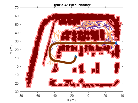
Plan and visualize the path for another set of start and goal poses.
% Define new start and goal poses
startPose = [30 -12 pi];
goalPose  = [-26 12 pi/2];
% Plan path
refPath = plan(planner,startPose,goalPose);
% Visualize the planned path.
figure(Name="Hybrid A* Planned Path",NumberTitle="on")
show(planner)
xlabel("X (m)")
ylabel("Y (m)")

Next Steps
This example showed how to plan a reference path for navigation of an autonomous vehicle in an NDT map using a Hybrid A* path planner. To safely navigate the vehicle on the planned path, you must localize the vehicle on an NDT map. For information on how to develop and evaluate a lidar localization algorithm, see Lidar Localization with Unreal Engine Simulation example.
See Also
Objects
vehicleCostmap|plannerHybridAStar(Navigation Toolbox) |validatorVehicleCostmap(Navigation Toolbox) |stateSpaceSE2(Navigation Toolbox)