Main Content

Discrete Impulse

Generate discrete impulse

  • Discrete Impulse block

Libraries:
DSP System Toolbox / Sources

Description

The Discrete Impulse block generates an impulse (the value 1) at output sample D+1, where you specify D using the Delay parameter (D0). All output samples preceding and following sample D+1 are zero.

When D is a length-N vector, the block generates an M-by-N matrix output representing N distinct channels, where you specify frame size M using the Samples per frame parameter. The impulse for the ith channel appears at sample D(i)+1.

The Sample time parameter value, Ts, specifies the output signal sample period. The resulting frame period is MTs.

Examples

expand all

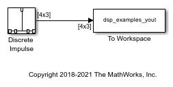
This example shows how to generate a discrete impulse signal with three channels and a data type of double. The Discrete Impulse block has the following settings:

  • Delay = [0 3 5]

  • Sample time = 0.25

  • Samples per frame = 4

  • Output data type = double

Run the model and look at the output, dsp_examples_yout. The first few samples of each channel are shown below:

dsp_examples_yout(1:10,:)
ans =
     1     0     0
     0     0     0
     0     0     0
     0     1     0
     0     0     0
     0     0     1
     0     0     0
     0     0     0
     0     0     0
     0     0     0

The block generates an impulse at sample 1 of channel 1 (first column), at sample 4 of channel 2 (second column), and at sample 6 of channel 3 (third column).

Ports

Output

expand all

Output signal containing a discrete impulse at output sample D(i)+1, where D is a scalar or vector specified by the Delay parameter. For more information, see Description.

Data Types: single | double | int8 | int16 | int32 | int64 | uint8 | uint16 | uint32 | uint64 | Boolean | fixed point

Parameters

expand all

Main

The number of zero-valued output samples, D, preceding the impulse, specified as a scalar or vector of integer values, greater than or equal to zero. A length-N vector specifies an N-channel output.

The sample period, Ts, of the output signal specified as a positive finite scalar. The output frame period is MTs.

The number of samples, M, in each output frame, specified as a positive integer scalar.

Data Types

Specify the output data type for this block. You can select one of the following:

  • A rule that inherits a data type, for example, Inherit: Inherit via back propagation. When you select this option, the output data type and scaling matches that of the next downstream block.

  • A built-in data type, such as double

  • An expression that evaluates to a valid data type, for example, fixdt(1,16)

For help setting data type parameters, display the Data Type Assistant by clicking the Show data type assistant button .

See Control Data Types of Signals (Simulink) for more information.

Data Type Assistant

Select how you would like to specify the data type properties of the Output data type. You can choose:

  • Inherit — Lets you specify a rule for inheriting a data type, for example, Inherit: Same as input

  • Built in— Lets you specify a built-in data type, for example, double

  • Fixed point — Lets you specify the fixed-point attributes of the data type.

  • Expression — Lets you specify an expression that evaluates to a valid data type, for example, fixdt(1,16)

For more information, see Specify Data Types Using Data Type Assistant (Simulink).

Specify whether the fixed-point data is signed or unsigned. Signed data can represent positive and negative values, but Unsigned data represents positive values only. For more information, see Specify Data Types Using Data Type Assistant (Simulink).

Specify the method for scaling your fixed-point data to avoid overflow conditions and minimize quantization errors. For more information, see Specify Data Types Using Data Type Assistant (Simulink).

Dependencies

To enable this parameter, set Mode to Fixed point

Specify the bit size of the word that holds the quantized integer as a positive integer from 2 to 128. For more information, see Specify Data Types Using Data Type Assistant (Simulink).

Dependencies

To enable this parameter, set Mode to Fixed point

Specify the fraction length of the fixed-point data type as a positive or negative integer scalar.

Dependencies

To enable this parameter, set Mode to Fixed point and Scaling to Binary point.

Select the data type override mode for this signal. You can select:

  • Inherit — Inherits the data type override setting specified for the model.

  • Off — Ignores the data type override setting specified for the model and uses the fixed-point data type you specify.

Dependencies

To enable this parameter, set Mode to Built in or Fixed point. For more information, see Specify Data Types Using Data Type Assistant (Simulink).

Block Characteristics

Data Types

Boolean | double | fixed point | integer | single

Direct Feedthrough

no

Multidimensional Signals

no

Variable-Size Signals

no

Zero-Crossing Detection

no

Extended Capabilities

C/C++ Code Generation
Generate C and C++ code using Simulink® Coder™.

Fixed-Point Conversion
Design and simulate fixed-point systems using Fixed-Point Designer™.

Version History

Introduced before R2006a