Classic IIR Filter Design
This example shows how to design classic IIR filters. The example initially focuses on the scenario where critical design parameter is the cutoff frequency at which the power of the filter decays to half (–3 dB) the nominal passband value.
The example then shows you how to replace a Butterworth design with a Chebyshev filter or an elliptic filter of the same order and obtain a steeper rolloff at the expense of some ripple in the passband and stopband of the filter. The example also explores minimum-order filter designs and tunable filters.
Lowpass Filters
Design an 8th order filter with a normalized cutoff frequency of 0.4𝜋. To begin, design a Butterworth filter which is maximally flat (no ripple in the passband or in the stopband).
N = 8;
F3dB = .4;
Hbutter = designfilt('lowpassiir',FilterOrder=N,HalfPowerFrequency=F3dB,...
    DesignMethod='butter',SystemObject=true);
A Chebyshev Type I filter has ripples in the passband and no ripples in the stopband. A Chebyshev Type I design allows you to control the passband ripples. Larger passband ripples result with a steeper rolloff.
Design a Chebyshev Type I filter with peak-to-peak ripples of 0.5 dB:
Ap = .5;
Hcheby1 = designfilt('lowpassiir',FilterOrder=N,HalfPowerFrequency=F3dB,...
    PassbandRipple=Ap,DesignMethod='cheby1',SystemObject=true);
hfvt = filterAnalyzer(Hbutter,Hcheby1);
setLegendStrings(hfvt,["Butterworth","Chebyshev Type I"]);

A Chebyshev Type II filter has ripples in the stopband, and no ripples in the passband. A Chebyshev Type II design allows you to control the stopband attenuation. A smaller stopband attenuation results with a steeper rolloff.
Design a Chebyshev Type II filter with a stopband attenuation of 80 dB:
Ast = 80;
Hcheby2 = designfilt('lowpassiir',FilterOrder=N,HalfPowerFrequency=F3dB,...
    StopbandAttenuation=Ast,DesignMethod='cheby2',SystemObject=true);
hfvt = filterAnalyzer(Hbutter,Hcheby2);
setLegendStrings(hfvt,["Butterworth","Chebyshev Type II"]);

Finally, an elliptic filter can provide a steeper rolloff compared to the previous designs by allowing ripples both in the stopband and the passband. To illustrate that, design an elliptic filter using the same passband and stopband characteristic as the previous steps.
Hellip = designfilt('lowpassiir',FilterOrder=N,HalfPowerFrequency=F3dB,...
    PassbandRipple=Ap,StopbandAttenuation=Ast,DesignMethod='ellip',SystemObject=true);
hfvt = filterAnalyzer(Hbutter,Hcheby1,Hcheby2,Hellip);
setLegendStrings(hfvt, ...
    ["Butterworth","Chebyshev Type I","Chebyshev Type II","Elliptic"]);

Zoom in on the passband to verify that all filters have the same –3dB frequency point and that only the Butterworth and the Chebyshev Type II designs have a perfectly flat passband.
Phase Consideration
If phase response is a design concern, it is useful to remember that Butterworth and Chebyshev Type II introduce less distortion (their group delay is flatter). Verify that by comparing the group delay responses of the four filters designed in the previous steps.
opts = filterAnalysisOptions("groupdelay");
setAnalysisOptions(hfvt,opts);
Minimum-Order Designs
Minimum order designs apply when the passband, stopband, and the magnitude of tolerable ripples are fully specified. In these cases, the cutoff frequency of 3dB is not of primary interest. The smallest filter order required to meet the design specification is automatically derived by the design algorithm.
Design a minimum-order IIR filter.
Fp = .1;
Fst = .3;
Ap = 1;
Ast = 60;
Hbutter = designfilt('lowpassiir',PassbandFrequency=Fp,StopbandFrequency=Fst,...
    PassbandRipple=Ap,StopbandAttenuation=Ast,DesignMethod='butter',SystemObject=true);
Hcheby1 = designfilt('lowpassiir',PassbandFrequency=Fp,StopbandFrequency=Fst,...
    PassbandRipple=Ap,StopbandAttenuation=Ast,DesignMethod='cheby1',SystemObject=true);
Hcheby2 = designfilt('lowpassiir',PassbandFrequency=Fp,StopbandFrequency=Fst,...
    PassbandRipple=Ap,StopbandAttenuation=Ast,DesignMethod='cheby2',SystemObject=true);
Hellip = designfilt('lowpassiir',PassbandFrequency=Fp,StopbandFrequency=Fst,...
    PassbandRipple=Ap,StopbandAttenuation=Ast,DesignMethod='ellip',SystemObject=true);
hfvt = filterAnalyzer(Hbutter);
showSpecificationMask(hfvt,true);
addFilters(hfvt,Hcheby1,Hcheby2,Hellip);
setLegendStrings(hfvt,["Butterworth","Chebyshev Type I","Chebyshev Type II","Elliptic"]);

A 7th order filter is necessary to meet the specification in the Butterworth design, whereas a 5th order filter is sufficient with the two Chebyshev techniques. Elliptic design reduces the required filter order even further to 4.
order(Hbutter)
ans =
7
order(Hcheby1)
ans =
5
order(Hcheby2)
ans =
5
order(Hellip)
ans =
4
Exact Matching of the Passband or Stopband Specifications
A minimum-order design often exceeds all the desired filter specifications, and has better ripples and a better transition width compared to what the user actually specified. Use the MatchExactly option to constrain the design specification to match exactly in at least one of the two bands. By default, Chebyshev Type I designs match the passband and exceed in the stopband. Butterworth and Chebyshev Type II designs match the stopband and exceed in the passband. Elliptic designs match the target attenuations in both bands, and exceed the stopband edge frequency.
Hellipmin1 = designfilt('lowpassiir',PassbandFrequency=Fp,StopbandFrequency=Fst,...
    PassbandRipple=Ap,StopbandAttenuation=Ast,MatchExactly='passband',...
    DesignMethod='ellip',SystemObject=true);
Hellipmin2 = designfilt('lowpassiir',PassbandFrequency=Fp,StopbandFrequency=Fst,...
    PassbandRipple=Ap,StopbandAttenuation=Ast,MatchExactly='stopband',...
    DesignMethod='ellip',SystemObject=true);
hfvt = filterAnalyzer(Hellip);
showSpecificationMask(hfvt,true);
addFilters(hfvt, Hellipmin1, Hellipmin2);
setLegendStrings(hfvt,["Matched passband and stopband", ...
    "Matched passband", "Matched stopband"])

Zoom in on the passband to compare the passband edges. The matched passband in both designs have an attenuation of exactly 1 dB at the passband edge frequency 0.1𝝅 rad/samples.
Verify that the resulting order of the filters did not change.
order(Hellip)
ans =
4
order(Hellipmin1)
ans =
4
order(Hellipmin2)
ans =
4
Highpass, Bandpass, and Bandstop Filters
You can generalize the results in the previous steps to highpass, bandpass, and bandstop response types. For example, design three minimum order bandpass filters.
Hbutter = designfilt('bandpassiir',StopbandFrequency1=.35,PassbandFrequency1=.45,...
    PassbandFrequency2=.55,StopbandFrequency2=.65,StopbandAttenuation1=60,PassbandRipple=1,...
    StopbandAttenuation2=60,DesignMethod='butter',SystemObject=true);
Hcheby1 = designfilt('bandpassiir',StopbandFrequency1=.35,PassbandFrequency1=.45,...
    PassbandFrequency2=.55,StopbandFrequency2=.65,StopbandAttenuation1=60,PassbandRipple=1,...
    StopbandAttenuation2=60,DesignMethod='cheby1',SystemObject=true);
Hcheby2 = designfilt('bandpassiir',StopbandFrequency1=.35,PassbandFrequency1=.45,...
    PassbandFrequency2=.55,StopbandFrequency2=.65,StopbandAttenuation1=60,PassbandRipple=1,...
    StopbandAttenuation2=60,DesignMethod='cheby2',SystemObject=true);
Hellip = designfilt('bandpassiir',StopbandFrequency1=.35,PassbandFrequency1=.45,...
    PassbandFrequency2=.55,StopbandFrequency2=.65,StopbandAttenuation1=60,PassbandRipple=1,...
    StopbandAttenuation2=60,DesignMethod='ellip',SystemObject=true);
hfvt = filterAnalyzer(Hbutter);
showSpecificationMask(hfvt,true);
addFilters(hfvt,Hcheby1,Hcheby2,Hellip);
setLegendStrings(hfvt,...
    ["Butterworth","Chebyshev Type I","Chebyshev Type II","Elliptic"])

Tunable IIR filters
In order to tune an IIR filter during simulation, create a dsp.SOSFilter object, and set the CoefficientSource property to 'Input port'.
sosFilt = dsp.SOSFilter;
You can use the design functions such as designLowpassIIR, designHighpassIIR, designBandpassIIR, designBandstopIIR to design lowpass, highpass, bandpass and bandstop IIR filters, respectively. The functions allow you to return the designed filter as a System object or return the filter coefficients as numerator and denominator matrices. In order to tune the filter coefficients during simulation, you can use the design functions to obtain the filter coefficients.
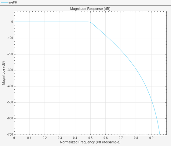
Use the designLowpassIIR function to design a lowpass filter of filter order of 30 and half-power frequency of 0.5 and set the obtained filter coefficients on the sosFilt object.
[b,a] = designLowpassIIR(FilterOrder=30,HalfPowerFrequency=0.5);
sosFilt.Numerator = b;
sosFilt.Denominator = a;
hfvt = filterAnalyzer(sosFilt);
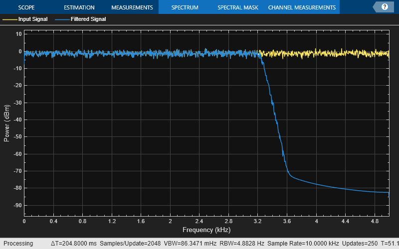
Create a spectrumAnalyzer object to visualize the spectrum of the input and output signals.
spectrumScope = spectrumAnalyzer(PlotAsTwoSidedSpectrum=false, ChannelNames=["Input Signal","Filtered Signal"]);
Vary the 3-dB cutoff frequency of the filter during simulation. The designLowpassIIR function redesigns the coefficients based on the updated filter specifications. Pass these updated coefficients to the SOS filter. Visualize the spectra of the input and filtered signals using the spectrum analyzer.
F3dB = 0.5;
for idx = 1:501
    if mod(idx,100)==0
        % Update filter specs once every 100 steps
        [b,a] = designLowpassIIR(FilterOrder=30,HalfPowerFrequency=F3dB,DesignMethod="butter");
        F3dB = F3dB + 0.05;
        sosFilt.Numerator = b;
        sosFilt.Denominator = a;
    end
    x = randn(1024,1);
    y = sosFilt(x);
    spectrumScope(x,y);
end