Biquad Filter
Libraries:
DSP HDL Toolbox /
Filtering
Description
A biquad filter is a form of infinite-impulse response (IIR) filter where the numerator and denominator are split into a series of second-order sections connected by gain blocks. This type of filter can replace a large FIR filter that uses an impractical amount of hardware resources. Designs often use biquad filters as DC blocking filters or to meet a specification originally implemented with an analog filter, such as a pre-emphasis filter.
Note
You can also generate HDL code for this hardware-optimized algorithm, without creating a Simulink® model, by using the DSP HDL IP Designer app. The app provides the same interface and configuration options as the Simulink block.
Examples
High Performance DC Blocker for FPGA
Create a DC blocking filter for a hardware communications system.
Choose Data Types for Biquad Filter
Choose fixed-point data types for biquad filter implementation on hardware.
Ports
Input
Output
Parameters
Note
These parameters apply when configuring a block in Simulink or an algorithm in the DSP HDL IP Designer app.
Main
Both the Direct form II and Direct form II
transposed architectures are pipelined and quantized to fit well into
FPGA DSP blocks. The output of these filters matches the output of the DSP System Toolbox™ System objects dsp.SOSFilter
and dsp.FourthOrderSectionFilter. These architectures minimize the number of
multipliers used by the filter but have a critical path through the feedback loop and
sometimes cannot achieve higher clock rates. These architectures do not support vector
input.
Pipelined feedback form implements a pipelined
architecture that uses more multipliers than either direct-form II structure, but
achieves higher clock rates after synthesis. Vector input is supported only when you
use Pipelined feedback form. The output of the pipelined
filter is slightly different than the DSP System Toolbox functions dsp.SOSFilter
and dsp.FourthOrderSectionFilter because of the timing of data samples applied
in the pipelined filter stages.
Direct form I fully serial implements a fully serial
architecture that uses only one multiplier. When you select this option, the block
stores the numerator, denominator, and scale values in the same ROM. You can control
the data type of the ROM by using the Coefficients data type
parameter. When you select this architecture, the output ready
port appears on the block. This architecture does not support vector input.
Specify the numerator coefficients as a matrix of NumSections-by-3 values. NumSections is the number of second-order filter sections. The block infers the number of filter sections from the size of the numerator and denominator coefficients. The numerator coefficient and denominator coefficient matrices must be the same size. The default filter has one section.
Specify the denominator coefficients as a matrix of
NumSections-by-3 values. The block assumes the first denominator
coefficient of each section is 1.0. NumSections
is the number of second-order filter sections. The block infers the number of sections
from the size of the numerator and denominator coefficients. The numerator coefficient
and denominator coefficient matrices must be the same size. The default filter has one
section.
Specify the gain values as a vector of up to NumSections+1 values. NumSections is the number of second-order filter sections. The block infers the number of sections from the size of the numerator and denominator coefficients. If the vector has only one value, the block applies that gain before the first section. If you specify fewer values than there are filter sections, the block sets the remaining section gain values to one. The diagram shows a 3-section filter and the locations of the four scale values before and after the sections.

Implementing these gain factors outside the filter sections reduces the multipliers needed to implement the numerator of the filter.
Data Types
Rounding mode for type-casting the output and accumulator values to the data types specified by the Output and Accumulator parameters. When the input data type is floating point, the block ignores this parameter. For more details, see Rounding Modes.
Overflow handling for type-casting the output and accumulator values to the data types specified by the Output and Accumulator parameters. When the input data type is floating point, the block ignores this parameter. For more details, see Overflow Handling.
The block casts the numerator coefficients to this data type. The quantization rounds to the nearest representable value and saturates on overflow. When the input data type is floating point, the block ignores this parameter.
The block returns a warning if the data type of the coefficients does not have enough fractional length to represent the coefficients accurately.
If you specify an unsigned data type for this parameter, the filter uses the unsigned values and converts them to a signed data type. The signed data type is required to map the design onto DSP slices on an FPGA.
Dependencies
To enable this parameter, set Filter structure to
Direct form II transposed, Direct form
II, or Pipelined feedback form.
The block casts the denominator coefficients to this data type. The quantization rounds to the nearest representable value and saturates on overflow. When the input data type is floating point, the block ignores this parameter.
The block returns a warning if the data type of the coefficients does not have enough fractional length to represent the coefficients accurately.
If you specify an unsigned data type for this parameter, the filter uses the unsigned values and converts them to a signed data type. The signed data type is required to map the design onto DSP slices on an FPGA.
Dependencies
To enable this parameter, set Filter structure to
Direct form II transposed, Direct form
II, or Pipelined feedback form.
The block casts the scale values to this data type. The quantization rounds to the nearest representable value and saturates on overflow. When the input data type is floating point, the block ignores this parameter.
Dependencies
To enable this parameter, set Filter structure to
Direct form II transposed, Direct form
II, or Pipelined feedback form.
The block casts the numerator, denominator, and scale values to this data type and stores them in an eight-element memory of this word length. The quantization rounds to the nearest representable value and saturates on overflow. When the input data type is floating point, the block ignores this parameter.
If you specify an unsigned data type for this parameter, the filter uses the unsigned values and converts them to a signed data type. The signed data type is required to map the design onto DSP slices on an FPGA.
Dependencies
To enable this parameter, set Filter structure to
Direct form I fully serial.
The block casts the internal accumulator signals (as indicated in the diagrams in the Algorithms section) to this data type. The quantization uses the settings of the Rounding mode and Saturate on integer overflow parameters. When the input data type is floating point, the block ignores this parameter.
The block casts the output of the filter to this data type. The quantization uses the settings of the Rounding mode and Saturate on integer overflow parameters. When the input data type is floating point, the block ignores this parameter.
Algorithms
The direct form II and direct form II transposed architectures are pipelined and quantized to fit well into FPGA DSP blocks. The architecture diagrams show the accumulator quantization points and pipeline registers for the direct form II and direct form II transposed architectures. The dashed lines indicate how the multiply-add operation fits into a DSP block on an FPGA.
|
|
|
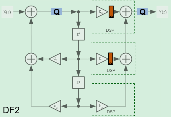
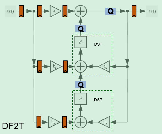
The transposed biquad filter implementations have a long critical path through the feedback loop between poles z-1 and z-2. They use the lowest number of multipliers but are not suitable for high-speed applications.
The pipelined biquad architecture uses more multipliers but reduces the critical path and achieves higher clock rates. The filter uses the Parhi method [1], which adds pipeline registers by increasing the order of the denominator, and then compensates for the modified denominator by adding poles in the numerator. The pipelined denominator uses order z-4 and z-8 rather than z-1 and z-2. Since the poles are less than one for a stable filter, the poles from the higher orders are smaller than the starting values, which adds to filter stability.
To support frame-based (vector) input, the pipelined architecture increases the order of
the denominator to the power of the input size. A frame-based pipelined denominator uses
z-N*4 and
z-N*8, where N is the
size of the input vector. The new numerator that compensates for the additional poles in the
denominator has 2*N*4-1 coefficients. This
implementation uses more resources but supports high-throughput applications.
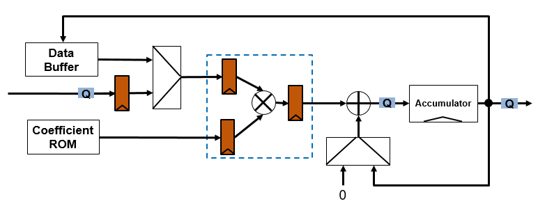
The fully serial architecture implements a direct form I architecture that uses one multiplier. The block stores the coefficients and scale values in a ROM that has eight-elements for each filter section. The data buffer stores the delay values for the input and output delay lines. The architecture diagram shows the quantization points and pipeline registers. The multiplier uses full-precision data types. The implementation quantizes the data path before the accumulator and the resulting data type at the output of the accumulator also applies to the data buffer. The multiplier is pipelined to fit to a DSP block on an FPGA, as shown by the dashed line box.
References
[1] Chung, Jin-Gyun, and Keshab K. Parhi. Pipelined Lattice and Wave Digital Recursive Filters. Boston: Springer US, 1996. https://doi.org/10.1007/978-1-4613-1307-6.