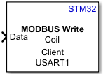
Contenuto principale

Modbus Write

Write data to server device register(s) over RS485 network

Since R2025a

  • MODBUS Write

Libraries:
STM32 Microcontroller Blockset / STM32F7xx Based Boards
STM32 Microcontroller Blockset / STM32G4xx Based Boards
STM32 Microcontroller Blockset / STM32H7xx Based Boards

Description

The Modbus Write block writes data to the register(s) of the server device.

The Modbus Write block accepts data of type uint16 for single register write operations and [Nx1] vector data of type uint16 for multiple register write operations.

STM32™ Microcontroller Blockset supports the Modbus® communication protocol over the RS485 network. The client and the server must be connected on the same RS485 network for successful Modbus communication. Each device on the RS485 network is referenced by a unique 8-bit address or identifier.

This table categories the server device registers referenced by the Modbus client device.

Register TypeRegister SizeAllowed Client Operation on Register
Coil1-bitRead and Write
Discrete Input1-bitRead
Holding Register16-bitRead and Write
Input Register16-bitRead

The client can perform either a read or a write operation (depending on the register type) on register(s) of a server device.

Note

Ensure that the number of client write registers does not exceed the server read register count.

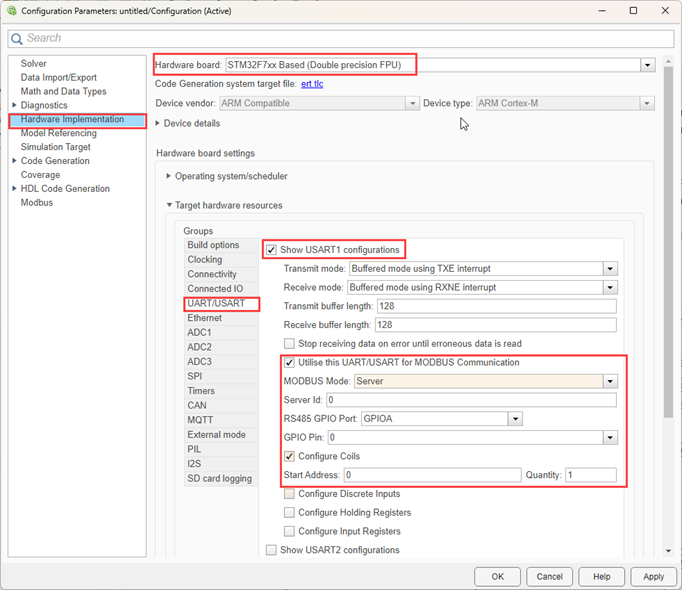
To enable the Modbus communication on a particular UART, navigate to the Configuration Parameters > Hardware Implementation > Target hardware resources > USART/UART properties of the model and perform the following:

  1. Enable the Modbus on required USART/UART peripheral.

  2. Select the MODBUS Mode parameter as Server or Client. If you set the MODBUS Mode to Server, configure the registers accordingly.

  3. Select the register type to configure and enter the register address in the Start address field. For more information, see UART/USART.

UART/USART Configuration

Examples

Ports

Input

expand all

The input to the block is the data to be written to the server register(s) by the client as a N-by-1 vector, where N represents the number of registers on the server device.

  • If you select the Coil or Discrete Input write operations, the client writes data to the server registers as a 1-bit write operation having the Boolean data type.

  • If you select the Holding Register or Input Register write operations, the client writes data to the server registers as a 16-bit write operation having the uint16 data type.

Data Types: Boolean | uint16

Parameters

expand all

Select the Modbus write block type.

Programmatic Use

Block Parameter: BlockTyp

Enter the unique 8-bit Modbus server ID or identifier to identify the server to which the client writes the data.

Programmatic Use

Block Parameter: ServerId

Select the type of write operation you want to perform on the server register(s). Specify any one of the following:

  • Coil: Write data to the coil register starting at the address specified in the Coil Address parameter.

  • Discrete input: Write data to the discrete input register starting at the address specified in the Discrete Input Address parameter. Writing data to the discrete input register address is not supported in client mode

  • Holding register: Write data to the holding register starting at the address specified in the Holding Register Address parameter.

  • Input register: Write data to the input register starting at the address specified in the Input Register Address parameter.

Programmatic Use

Block Parameter: RegType

Specify the start address to execute the write operation. Use zero-based indexing; for example, to read from the 10th location, specify the value as 9.

Programmatic Use

Block Parameter: WriteAddress

Specify the number of registers the client writes data to. For example, for the client to write data from the coil registers with location ranging from 10 to 14, enter 5.

Programmatic Use

Block Parameter: Number

Configure the USART or UART module for MODBUS communication.

To enable read of a particular register, navigate to the Configuration Parameters > Hardware Implementation > Target hardware resources > USART/UART properties.

Programmatic Use

Block Parameter: UARTModule

Amount of time in seconds that the model waits for data during each simulation time step.

Programmatic Use

Block Parameter: Timeout

Enter the time interval (in seconds) at which the client writes data from the server device register(s).

Programmatic Use

Block Parameter: SampleTime

Version History

Introduced in R2025a