Generate C Timer Service Interface Code for Component Deployment
This example shows how to generate calls to a target platform timer service function to get the value of the target environment function clock tick for an aperiodic component. The generated interface code must align with the environment-specific service function prototype and data communication method.
In the example you:
Represent a timer service request in the top model.
Configure the code generator to apply the default timer service code interface.
Generate and inspect the interface code.
Configure the timer service code interface for during-execution data access.
Regenerate and reinspect the interface code.
Represent Request for Function Clock Tick in Top Model
Open example component model ComponentDeploymentFcn.
open_system('ComponentDeploymentFcn');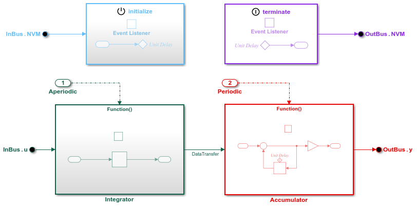
To model requests for the value of a target environment function clock tick, include a Discrete Time Integrator or Weighted Sample Time block in a top model function. In this example model, the aperiodic integrator function includes a Discrete Time Integrator block.
Open the function-call subsystem Integrator.

The function applies a forward integration method and a gain value of 1.25 to the value of state variable x each time the function executes.
Configure Timer Service Code Interface
The example model is linked to the shared Embedded Coder Dictionary file ComponentDeploymentCoderDictionary.sldd, which defines a service code interface configuration. That configuration defines the timer service interfaces get_tick_outside and get_tick_during. Interface function get_tick_outside, the default, specifies outside-execution data communication. Interface get_tick_during specifies during-execution data communication. Both interfaces specify naming rule $G$X, where $G is the service interface name and $X is the name of the callable entry-point function requesting the tick value.
Configure the model such that the code generator applies the coder dictionary default interface for accessing the function clock tick value.
Open the Embedded Coder app.
Select Code Interface > Component Interface.
In the Code Mappings editor, click the Functions tab.
Select the row for
Exported Function:Aperiodicand click the pencil icon.In the dialog box that appears, set the Timer Service property to
Dictionary default: get_tick_outside. As the name indicates, the default interface is configured to use outside-execution data communication. Alternatively, you can set the property in the Property Inspector.Save the configuration change by saving the model.
Generate and Inspect Interface Code
Generate code from the example model. The code generator creates the folder ComponentDeploymentFcn_ert_rtw in the current working folder and places source code files in that folder. The generated code is in two primary files: header file ComponentDeploymentFcn.h and source code file ComponentDeploymentFcn.c. Model data and entry-point functions are accessible to a caller by including the header file target environment software.
The code generator also produces an interface header file, which by default the code generator names services.h. This file includes declarations for platform service interface functions called by the component code.
To inspect the generated code, use the generated Code Interface Report or, in the Embedded Coder app, use the Code view. The report is helpful for verifying that the generated interface code aligns with code interface requirements. The report provides the timer service interface information in the section for the function that calls the service function. Information provided includes:
Timer function prototype
Data communication method used
Service header file that declares the interface function prototype
Header File
The header file ComponentDeploymentFcn.h includes interface header file services.h, defines an instance of the real-time model data structure, and declares structures and callable entry-point functions for data and function interface elements represented in the model.
This code fragment shows lines of code in the header file that are relevant to function clock tick requests: the inclusion of services.h, variable declarations, and the a declaration for the generated entry-point function that calls the timer service function.
#include "services.h"
.
.
.
typedef struct {
  real_T DataTransfer_WriteBuf[10];
  real_T DiscreteTimeIntegrator_PREV_U[10];
  uint32_T Interator_PREV_T;
  uint8_T DiscreteTimeIntegrator_SYSTEM_E;
  boolean_T Integrator_RESET_ELAPS_T;
} D_Work;

typedef struct {
  real_T delay[10];
  real_T dti[10];
} CD_measured_T;
.
.
.
extern void CD_integrator(void);
Source Code File
When the model is configured for the code generator to produce interface code that uses outside-execution data communication, the integrator entry-point function in the generated source code file ComponentDeploymentFcn.c calls target platform timer service function get_tick_outside_CD_integrator.
When a service interface uses the outside-execution data communication method, calls to the service function take no arguments.
CD_measured_T CD_measured;
.
.
.
void CD_integrator(void)
{
  real_T tmp;
  real_T *tmp_0;
  int32_T i;
  uint32_T Integrator_ELAPS_T;
  tmp_0 = set_CD_integrator_DataTransfer();
  if (rtDwork.Integrator_RESET_ELAPS_T) {
    Integrator_ELAPS_T = 0U;
  } else {
    Integrator_ELAPS_T = (uint32_T)(get_tick_outside_CD_integrator() -
      rtDWork.Integrator_PREV_T);
  }

  rtDWork.Integrator_PREV_T = get_tick_outside_CD_integrator();
  rtDwork.Integrator_RESET_ELAPS_T = false;
  tmp = 1.25 * (real_T)Integrator_ELAPS_T;
  for (i = 0; i < 10; i++) {
    if ((int32_T)rtDWork.DiscreteTimeIntegrator_SYSTEM_E == 0) {
      CD_measured.dti[i] += tmp * rtDWork.DiscreteTimeIntegrator_PREV_U[i];
    }

    rtDWork.DiscreteTimeIntegrator_PREV_U[i] = (get_CD_integrator_InBus_u())[i];
}

  rtDWork.DiscreteTimeIntegrator_SYSTEM_E = 0U;
  memcpy(&tmp_0[0], &CD_measured.dti[0], (uint32_T)(10U * sizeof(real_T)));
}
The integrator function calls the timer service function get_tick_outside_CD_integrator to get the current tick value to use for calculating the current elapsed time and to cache the previous tick value.
The code generator assumes that the resolution of the clock is the fundamental step size of the model.
Services Header File
Services header file services.h declares prototypes for calling services that run as platform software in a target environment. This code fragment shows the prototype declaration for calling timer service function.
/* timer services */
extern uin32_T get_tick_outside_CD_integrator(void);
For an interface that uses the outside-execution data communication method, the code generator expects the target environment to provide a buffer for data communication. Because the target environment software creates and manages access to the buffer, the timer service function takes no arguments.
The function name reflects the naming rule defined for the timer service interface in the linked Embedded Coder Dictionary. The naming rule $G$X instructs the code generator to replace $G with the name of the service interface (get_tick_outside) and $X with the name of the calling entry-point function (CD_integrator).
Configure Timer Code Interface for During-Execution Data Access
Configure the example model such that the code generator applies the coder dictionary interface for during-execution access to the function clock tick value.
If the Embedded Coder app is not open, open it and select Code Interface > Component Interface.
In the Code Mappings editor, click the Functions tab.
Select the row for
Exported Function:Aperiodicand click the pencil icon.In the dialog box that appears, set the Timer Service property to
get_tick_during. As the name indicates, the default interface is configured to use during-execution data communication. Alternatively, you can set the property in the Property Inspector.Save the configuration change by saving the model.
Regenerate and Reinspect Interface Code
Regenerate code from the example model.
The generated code shown in the following sections assumes that you have configured the inports, outports, data transfers, and the timer service for the integrator function with a service interface that applies the during-execution data communication method.
Header File
The lines of code relevant to the timer code interface in the header file ComponentDeploymentFcn.h are the same as for the outside-execution timer code interface.
#include "services.h"
.
.
.
typedef struct {
  real_T DataTransfer_WriteBuf[10];
  real_T DiscreteTimeIntegrator_PREV_U[10];
  uint32_T Interator_PREV_T;
  uint8_T DiscreteTimeIntegrator_SYSTEM_E;
  boolean_T Integrator_RESET_ELAPS_T;
} D_Work;

typedef struct {
  real_T delay[10];
  real_T dti[10];
} CD_measured_T;
.
.
.
struct tag_RTM {
  struct {
    uint32_T clockTick2;
    .
    .
    .
  } Timing;
};
.
.
.
extern void CD_integrator(void);
Source Code File
When the model is configured for the code generator to produce interface code that uses during-execution data communication, the integrator entry-point function in the generated source code file ComponentDeploymentFcn.c calls target platform timer service function get_tick_during_CD_integrator.
When using the during-execution data communication method, calls to the service function take a pointer to a buffer in the generated code as an argument.
void CD_integrator(void)
{
  real_T tmp[10];
  real_T tmp_0;
  int32_T i;
  uint32_T Integrator_ELAPS_T;
  rtM->Timing.clockTick2 = get_tick_during_CD_integrator();
  if (rtDWork.Interator_RESET_ELAPS_T) {
    Integrator_ELAPS_T = 0U;
  } else {
    Integrator_ELAPS_T = (uint32_T)(rtM->Timing.clockTick2 -
      rtDWork.Integrator_PREV_T);
  }

  get_CD_integrator_input_(&tmp[0]);
  rtDWork.Integrator_PREV_T = rtM->Timing.clockTick2;
  rtDWork.Integrator_RESET_ELAPS_T = false;
  tmp_0 = 1.25 * (real_T)Integrator_ELAPS_T;
  for (i = 0; i < 10; i++) {
    if ((int32_T)rtDWork.DiscreteTimeIntegrator_SYSTEM_E == 0) {
      CD_measured.dti[i] += tmp_0 * rtDWork.DiscreteTimeIntegrator_PREV_U[i];
    }

    rtDWork.discreteTimeIntegrator_PREV_U[i] = tmp[i];
}

  rtDWork.DiscreteTimeIntegrator_SYSTEM_E = 0U;
  set_CD_integrator_DataTransfer(CD_measured.dti);
}
When using the during-execution data communication method, the generated code calls the timer service function get_tick_during_CD_integrator to get the current tick value to use for calculating the current elapsed time.
The code generator assumes that the resolution of the clock is the fundamental step size of the model.
Services Header File
This code fragment shows the prototype declaration for calling the timer service function when using during-execution data communication.
/* timer services */
extern uint32_T get_tick_during_CD_integrator(void);
Like when using the outside-execution data communication method, the code generator expects the target environment to provide a buffer for data communication. Because the target environment software creates and manages access to the buffer, the timer service function takes no arguments.
The function name reflects the naming rule defined for the timer service interface in the linked Embedded Coder Dictionary. The naming rule $G$X instructs the code generator to replace $G with the name of the service interface (get_tick_during) and $X with the name of the calling entry-point function (CD_integrator).