importhdl
Import Verilog or VHDL code and generate Simulink model
Description
importhdl( imports the
specified HDL files and generates the corresponding Simulink® model while removing unconnected components that do not directly
contribute to the output.FileNames)
importhdl(
imports the specified HDL files and generates the corresponding Simulink model while removing unconnected components that do not directly
contribute to the output, with options specified by one or more name-value pair
arguments.FileNames,Name=Value)
Examples
This example shows how you can import a file containing Verilog code and generate the corresponding Simulink™ model. The Verilog code in this example infers a simple Compare to Constant block in your model
Specify Input Verilog File
Make sure that the input HDL file does not contain any syntax errors, is synthesizable, and uses constructs that are supported by HDL import. This example shows a Verilog code that performs a comparison.
edit('comparator.v')
// File Name: comparator.v
// This module implements a simple comparator module

`define value 12
module comparator (clk, rst, a, b);

input clk, rst;
input [3:0] a;
output reg [3:0] b;

always@(posedge clk) begin
    if (rst)
        b <= 0;
    else if (a < `value)
        b <= a + 1;
end

endmodule
Import Verilog File
To import the HDL file and generate the Simulink™ model, pass the file name as a character vector to the importhdl function.
importhdl('comparator.v');
### Parsing <a href="matlab:edit('comparator.v')">comparator.v</a>.
### Top Module name: 'comparator'.
### Identified ClkName::clk.
### Identified RstName::rst.
### Hdl Import parsing done.
### Removing unconnected components.
### Creating Target model comparator
### Begin model generation 'comparator'...
### Rendering DUT with optimization related changes (IO, Area, Pipelining)...
### Start Layout...
### Working on hierarchy at ---> 'comparator'.
### Laying out components.
### Working on hierarchy at ---> 'comparator/comparator'.
### Laying out components.
### Drawing block edges...
### Drawing block edges...
### Model generation complete.
### Setting model parameters.
### Generated model file C:\Users\user\OneDrive - MathWorks\Documents\MATLAB\ExampleManager\user.Bdoc.May28\hdlcoder-ex77699673\hdlimport\comparator\comparator.slx.
### Importhdl completed.
HDL import parses the input file and displays messages of the import process in the MATLAB™ Command Window. The import provides a link to the generated Simulink™ model comparator.slx. The generated model uses the same name as the name of the input Verilog file.
Examine Generated Simulink™ Model
To open the generated Simulink™ model, select the link. The model is saved in the hdlimport/comparator path relative to the current folder. You can simulate the model and observe the simulation results.
addpath('hdlimport/comparator');
open_system('comparator.slx');
sim('comparator.slx');
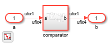
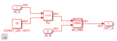
The top-level DUT Subsystem name is the same as the top-level module name in the input file. You see that the import inferred a Compare to Constant block from the input Verilog code.
open_system('comparator/comparator')

This example shows how you can import a VHDL file and generate the corresponding Simulink model. The VHDL code in this example is a simple 4-bit counter.
Specify Input VHDL File
Make sure that the input HDL file does not contain any syntax errors, is synthesizable, and uses constructs that importhdl function supports. The VHDL code in this example performs a 4-bit counter.
edit('counter.vhd')
library IEEE;
use IEEE.STD_LOGIC_1164.ALL;
use IEEE.NUMERIC_STD.ALL;
entity Counter is
    Port (
        clk : in STD_LOGIC;
        rst : in STD_LOGIC;
        count : out STD_LOGIC_VECTOR(3 downto 0)
    );
end Counter;
architecture Behavioral of Counter is
    signal temp_count : STD_LOGIC_VECTOR(3 downto 0) := "0000";
begin
    process(clk, rst)
    begin
        if rst = '1' then
            temp_count <= "0000";
        elsif rising_edge(clk) then
            if temp_count = "1111" then
                temp_count <= "0000";
            else
                temp_count <= temp_count + 1;
            end if;
        end if;
    end process;
    count <= temp_count;
end Behavioral;
Import VHDL File
To import the HDL file and generate the Simulink™ model, pass the file name as a character vector to the importhdl function.
importhdl('counter.vhd');
### Parsing <a href="matlab:edit('counter.vhd')">counter.vhd</a>.
### Top Module name: 'counter'.
### Identified ClkName::clk.
### Identified RstName::rst.
### Hdl Import parsing done.
### Removing unconnected components.
### Creating Target model counter
### Begin model generation 'counter'...
### Rendering DUT with optimization related changes (IO, Area, Pipelining)...
### Start Layout...
### Working on hierarchy at ---> 'counter'.
### Laying out components.
### Working on hierarchy at ---> 'counter/counter'.
### Laying out components.
### Drawing block edges...
### Drawing block edges...
### Model generation complete.
### Setting model parameters.
### Generated model file C:\Users\user\OneDrive - MathWorks\Documents\MATLAB\ExampleManager\user.Bdoc.Jul3\hdlcoder-ex36839477\hdlimport\counter\counter.slx.
### Importhdl completed.
the importhdl function parses the input file and displays messages about the import process in the MATLAB Command Window. The import links to the generated Simulink model counter.slx. The generated model uses the same name as the input VHDL file.
Open Generated Simulink™ Model
To open the generated Simulink™ model, click the link. The function saves the model in the hdlimport/counter path relative to the current folder. You can simulate the model and observe the simulation results.
addpath('hdlimport/counter');
open_system('counter.slx');
sim('counter.slx');
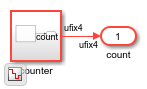
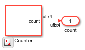
The top-level DUT subsystem name is the same as the top-level module name in the input file. The importhdl function chooses the Counter block to represent the VHDL code.
open_system('counter/counter')
This example shows how you can import multiple files containing Verilog code and generate the corresponding Simulink™ model.
Specify input Verilog File
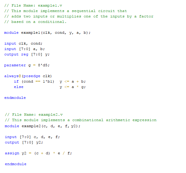
Make sure that the input HDL files do not contain any syntax errors, are synthesizable, and use constructs that are supported by HDL import. For example, this code shows three Verilog files that use module instantiation to form a hierarchical design. One module example1.v implements a simple sequential circuit based on an if-else condition. The other module example2.v implements a simple combinational arithmetic expression.
edit('example1.v')
edit('example2.v')
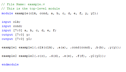
A top module contained in file example.v instantiates the two modules in example1.v and example2.v
edit('example.v')
Import Verilog Files
To import the HDL file and generate the Simulink™ model, pass the file names as a cell array of character vectors to the importhdl function. By default, HDL import identifies the top module and clock bundle when parsing the input file.
importhdl({'example.v','example1.v','example2.v'})
### Parsing <a href="matlab:edit('example.v')">example.v</a>.
### Parsing <a href="matlab:edit('example1.v')">example1.v</a>.
### Parsing <a href="matlab:edit('example2.v')">example2.v</a>.
### Top Module of the source: 'example'.
### Identified ClkName::clk.
### Hdl Import parsing done.
### Creating Target model example
### Generating Dot Layout...
### Start Layout...
### Working on hierarchy at ---> 'example'.
### Laying out components.
### Working on hierarchy at ---> 'example/example'.
### Laying out components.
### Working on hierarchy at ---> 'example/example/example1'.
### Laying out components.
### Applying Dot Layout...
### Drawing block edges...
### Working on hierarchy at ---> 'example/example/example2'.
### Laying out components.
### Applying Dot Layout...
### Drawing block edges...
### Applying Dot Layout...
### Drawing block edges...
### Applying Dot Layout...
### Drawing block edges...
### Setting the model parameters.
### Generated model as C:\Temp\examples\examples\hdlcoder-ex56732899\hdlimport\example\example.slx.
### HDL Import completed.
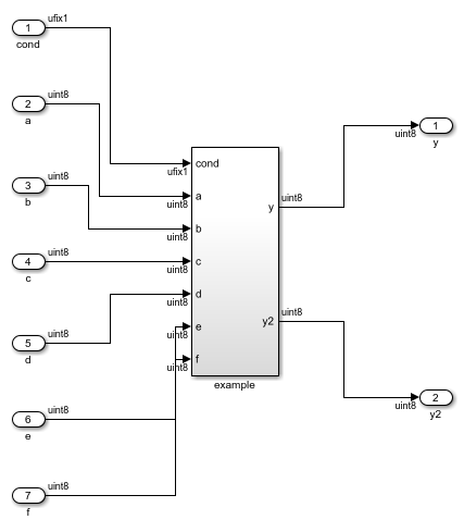
HDL import parses the input file and displays messages of the import process in the MATLAB™ Command Window. The import provides a link to the generated Simulink™ model example.slx. The generated model uses the same name as the top module that is contained in the input Verilog file example1.v.
Examine Generated Simulink™ Model
To open the generated Simulink™ model, select the link. The model is saved in the hdlimport/example path relative to the current folder. You can simulate the model and observe the simulation results.
addpath('hdlimport/example')
open_system('example.slx')
To avoid a division by zero, you can suppress the warning diagnostic before simulation.
Simulink.suppressDiagnostic({'example/example/example2/Div'}, ...
                                'SimulinkFixedPoint:util:fxpDivisionByZero')
sim('example')
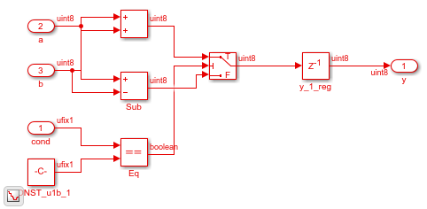
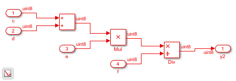
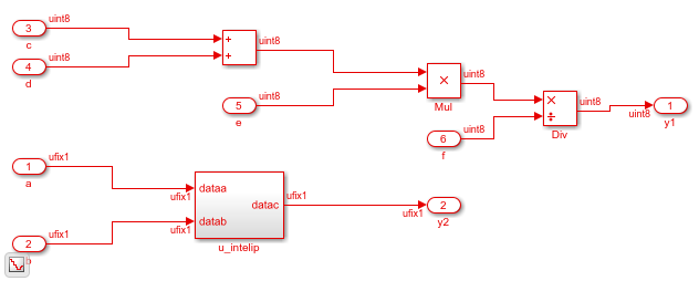
You can see the hierarchy of Subsystems that implement the Verilog code that uses module instantiation.
open_system('example/example/example1')
open_system('example/example/example2')
This example shows how you can import multiple files containing Verilog code and generate the corresponding Simulink™ model. When you import multiple files, if you want to obfuscate the HDL code or if your files contain HDL code for vendor-specific IPs, you can import the HDL code as a BlackBox module using the importhdl function.
Specify input Verilog Files
Make sure that the input HDL files do not contain any syntax errors, are synthesizable, and use constructs that are supported by HDL import. For example, this code shows three Verilog files that use module instantiation to form a hierarchical design. One module sequentialexp.v implements a simple sequential circuit based on an if-else condition. The other module comditionalcomb.v implements a simple combinational arithmetic expression.
edit('conditionalcomb.v')
edit('sequentialexp.v')
edit('intelip.v')
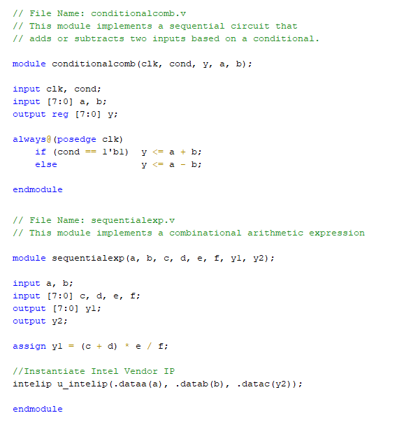
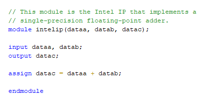
See that the sequentialexp.v module instantiates an Intel® IP that implements a single-precision floating-point adder.
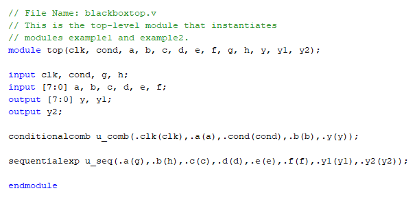
A top module top contained in file blackboxtop.v instantiates the two modules in conditionalcomb.v and sequentialexp.v
edit('blackboxtop.v')
Import Verilog Files
To import the HDL file and generate the Simulink™ model, pass the file names as a cell array of character vectors to the importhdl function. By default, HDL import identifies the top module and clock bundle when parsing the input file.
importhdl({'blackboxtop.v','conditionalcomb.v','sequentialexp.v','intelip.v'}, ...
                            'topModule','top','blackBoxModule','intelip')
### Parsing <a href="matlab:edit('blackboxtop.v')">blackboxtop.v</a>.
### Parsing <a href="matlab:edit('conditionalcomb.v')">conditionalcomb.v</a>.
### Parsing <a href="matlab:edit('sequentialexp.v')">sequentialexp.v</a>.
### Parsing <a href="matlab:edit('intelip.v')">intelip.v</a>.
### Top Module of the source: 'top'.
### Identified ClkName::clk.
### Hdl Import parsing done.
### Creating Target model top
### Generating Dot Layout...
### Start Layout...
### Working on hierarchy at ---> 'top'.
### Laying out components.
### Working on hierarchy at ---> 'top/top'.
### Laying out components.
### Working on hierarchy at ---> 'top/top/u_comb'.
### Laying out components.
### Applying Dot Layout...
### Drawing block edges...
### Working on hierarchy at ---> 'top/top/u_seq'.
### Laying out components.
### Working on hierarchy at ---> 'top/top/u_seq/u_intelip'.
### Laying out components.
### Applying Dot Layout...
### Drawing block edges...
### Applying Dot Layout...
### Drawing block edges...
### Applying Dot Layout...
### Drawing block edges...
### Applying Dot Layout...
### Drawing block edges...
### Setting the model parameters.
### Generated model as C:\Temp\examples\examples\hdlcoder-ex63017378\hdlimport\top\top.slx.
### HDL Import completed.
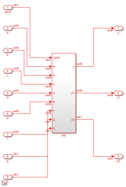
HDL import parses the input file and displays messages of the import process in the MATLAB™ Command Window. The import provides a link to the generated Simulink™ model top.slx. The generated model uses the same name as the top module that is contained in the input Verilog file conditionalcomb.v.
Examine Generated Simulink™ Model
To open the generated Simulink™ model, select the link. The model is saved in the hdlimport/top path relative to the current folder. You can simulate the model and observe the simulation results.
addpath('hdlimport/top')
open_system('top.slx')
set_param('top','SimulationCommand','update')
To avoid a division by zero, you can suppress the warning diagnostic before simulation.
Simulink.suppressDiagnostic({'top/top/u_seq/Div'}, ...
                                'SimulinkFixedPoint:util:fxpDivisionByZero')
sim('top')
You can see the hierarchy of Subsystems that implement the Verilog code that uses module instantiation.
open_system('top/top/u_comb')

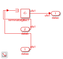
If you open the Subsystem that implements the sequential circuit, you can open the u_intelip Subsystem to see the blackbox implementation.
open_system('top/top/u_seq')
open_system('top/top/u_seq/u_intelip')
This example shows how you can import VHDL code that contains various arithmetic and logic operators and generate the corresponding Simulink model.
Specify Input VHDL File
Make sure that the input VHDL file does not contain any syntax errors, is synthesizable, and uses constructs for the various operators.
edit('operator.vhd')
library IEEE;
use IEEE.STD_LOGIC_1164.ALL;
use IEEE.STD_LOGIC_ARITH.ALL;
use IEEE.STD_LOGIC_UNSIGNED.ALL;

entity Operator is
    Port ( A : in  STD_LOGIC_VECTOR(3 downto 0);
           B : in  STD_LOGIC_VECTOR(3 downto 0);
           OpSelect : in STD_LOGIC_VECTOR(2 downto 0);
           Result : out STD_LOGIC_VECTOR(3 downto 0));
end Operator;

architecture Behavioral of Operator is
begin
    process(A, B, OpSelect)
    begin
        case OpSelect is
            when "000" => -- Addition
                Result <= A + B;
            when "001" => -- Subtraction
                Result <= A - B;
            when "010" => -- Bitwise AND
                Result <= A and B;
            when "011" => -- Bitwise OR
                Result <= A or B;
            when "100" => -- Bitwise XOR
                Result <= A xor B;
            when others => -- Default case
                Result <= not (A + B);
        end case;
    end process;
end Behavioral;
This VHDL code has various operators, such as:
Add
Subtract
Bitwise AND
Bitwise OR
Bitwise XOR
Bitwise NOT
It uses case statement to control the output signal.
Import VHDL File
To import the HDL file and generate the Simulink™ model, pass the file name as a character vector to the importhdl function.
importhdl('operator.vhd')
### Parsing <a href="matlab:edit('operator.vhd')">operator.vhd</a>.
### Top Module name: 'operator'.
### Hdl Import parsing done.
### Removing unconnected components.
### Creating Target model operator
### Begin model generation 'operator'...
### Rendering DUT with optimization related changes (IO, Area, Pipelining)...
### Start Layout...
### Working on hierarchy at ---> 'operator'.
### Laying out components.
### Working on hierarchy at ---> 'operator/operator'.
### Laying out components.
### Drawing block edges...
### Drawing block edges...
### Model generation complete.
### Generated model file C:\Users\user\OneDrive - MathWorks\Documents\MATLAB\ExampleManager\user.Bdoc.Jul3\hdlcoder-ex18098826\hdlimport\operator\operator.slx.
### Importhdl completed.
The importhdl function parses the input file and displays messages about the import process in the MATLAB Command Window. The import provides a link to the generated Simulink model operator.slx. The generated model uses the same name as the top module in the input VHDL file.
Open Generated Simulink™ Model
To open the generated Simulink™ model, select the link. The function saves the model in the hdlimport/operator path relative to the current folder. You can simulate the model and observe the simulation results.
addpath('hdlimport/operator')
open_system('operator.slx')

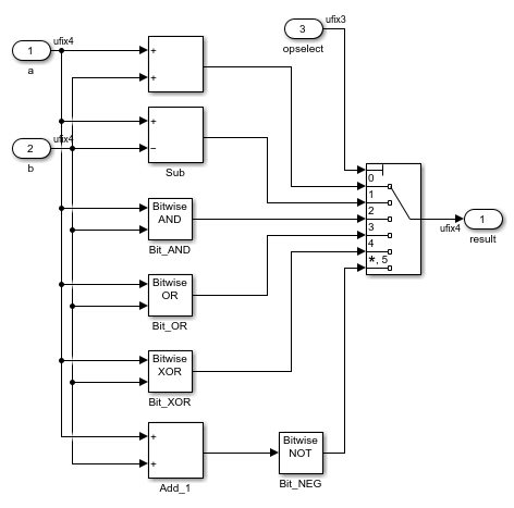
To represent the functionality of the VHDL code, the import function chose various mathematical and logical operation blocks and used a Multiport Switch block for the case statement logic.
open_system('operator/operator')
This example shows how you can import Verilog code that contains these operators and generate the corresponding Simulink™ model:
Arithmetic
Logical
XOR
Bitwise
Conditional
Relational
Concatenation
Specify Input Verilog File
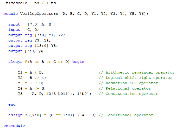
Make sure that the input HDL file does not contain any syntax errors, is synthesizable, and uses constructs for the various operators. For example, this Verilog code shows various operators.
edit('VerilogOperators.v')
Import Verilog File
To import the HDL file and generate the Simulink™ model, pass the file name as a character vector to the importhdl function.
importhdl('VerilogOperators.v')
### Parsing <a href="matlab:edit('VerilogOperators.v')">VerilogOperators.v</a>.
### Top Module of the source: 'VerilogOperators'.
### Hdl Import parsing done.
### Creating Target model VerilogOperators
### Generating Dot Layout...
### Start Layout...
### Working on hierarchy at ---> 'VerilogOperators'.
### Laying out components.
### Working on hierarchy at ---> 'VerilogOperators/VerilogOperators'.
### Laying out components.
### Applying Dot Layout...
### Drawing block edges...
### Applying Dot Layout...
### Drawing block edges...
### Generated model as C:\Temp\examples\examples\hdlcoder-ex29847655\hdlimport\VerilogOperators\VerilogOperators.slx.
### HDL Import completed.
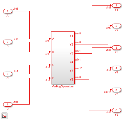
HDL import parses the input file and displays messages of the import process in the MATLAB™ Command Window. The import provides a link to the generated Simulink™ model VerilogOperators.slx. The generated model uses the same name as the top module in the input Verilog file.
Examine Generated Simulink™ Model
To open the generated Simulink™ model, select the link. The model is saved in the hdlimport/VerilogOperators path relative to the current folder. You can simulate the model and observe the simulation results.
addpath('hdlimport/VerilogOperators')
open_system('VerilogOperators.slx')
sim('VerilogOperators.slx')
This example shows how you can import multiple files containing Verilog code that perform implicit data type conversions and generate the corresponding Simulink™ model. HDL import can perform implicit data type conversion such as in arithmetic operations, data type conversion, bit selection, and bit concatenation.
Specify input Verilog File
Make sure that input HDL files do not contain any syntax errors, are synthesizable, and use constructs that are supported by HDL import. For example, this code shows three Verilog files that use module instantiation to form a hierarchical design. The modules NG1_implicit.v and round_const.v perform implicit data type conversion.
edit('NG1_implicit.v')
edit('round_constant.v')
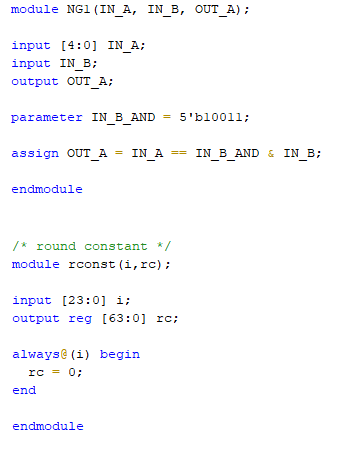
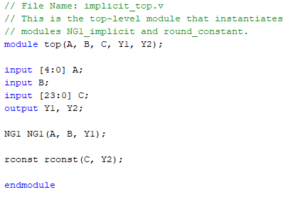
A top module contained in file example.v instantiates the two modules in NG1_implicit.v and round_constant.v.
edit('implicit_top.v')
Import Verilog Files
To import the HDL file and generate the Simulink™ model, pass the file names as a cell array of character vectors to the importhdl function. By default, HDL import identifies the top module when parsing the input file.
importhdl({'implicit_top.v','NG1_implicit.v','round_constant.v'})
### Parsing <a href="matlab:edit('implicit_top.v')">implicit_top.v</a>.
### Parsing <a href="matlab:edit('NG1_implicit.v')">NG1_implicit.v</a>.
### Parsing <a href="matlab:edit('round_constant.v')">round_constant.v</a>.
### Top Module name: 'top'.
Warning: Unused input port 'i' in 'rconst' module.
### Hdl Import parsing done.
### Creating Target model top
### Generating Dot Layout...
### Start Layout...
### Working on hierarchy at ---> 'top'.
### Laying out components.
### Working on hierarchy at ---> 'top/top'.
### Laying out components.
### Working on hierarchy at ---> 'top/top/NG1'.
### Laying out components.
Configurable Subsystem block 'simulink/Ports & Subsystems/Configurable Subsystem' must be converted to a Variant Subsystem block. Variant subsystems offers enhanced capabilities while maintaining equivalant functionality. Support of Configurable Subsystem will be removed in a future release.

### Applying Dot Layout...
### Drawing block edges...
### Working on hierarchy at ---> 'top/top/rconst'.
### Laying out components.
### Applying Dot Layout...
### Drawing block edges...
### Applying Dot Layout...
### Drawing block edges...
### Applying Dot Layout...
### Drawing block edges...
### Generated model file C:\TEMP\Examples\hdlcoder-ex12503110\hdlimport\top\top.slx.
### Importhdl completed.
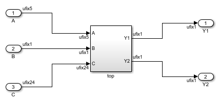
HDL import parses the input file and displays messages of the import process in the MATLAB™ Command Window. The import provides a link to the generated Simulink™ model implicit_top.slx. The generated model uses the same name as the top module that is contained in the input Verilog file implicit_top.v.
Examine Generated Simulink™ Model
To open the generated Simulink™ model, select the link. The model is saved in the hdlimport/example path relative to the current folder. You can simulate the model and observe the simulation results.
addpath('hdlimport/top');
open_system('top.slx')
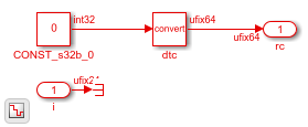
In the rconst Subsystem, one of the input ports is unconnected. It is good practice to avoid unterminated outputs by adding a Terminator block.
addterms('top');
sim('top');
You can see the hierarchy of Subsystems that implement the Verilog code that uses module instantiation.
open_system('top/top/NG1')
open_system('top/top/rconst')
This example shows how you can import a file containing Verilog code and infer RAM blocks in the Simulink™ model that gets generated. You can import Verilog code that infers any of the various RAMs in the HDL RAMs library including the hdl.RAM System-Object based blocks and Block RAMs.
Specify Input Verilog File
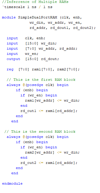
Make sure that the input HDL file does not contain any syntax errors, is synthesizable, and uses constructs that are supported by HDL import. This example shows the Verilog code.
edit('simple_dual_port_ram.v')
Import Verilog File
To import the HDL file and generate the Simulink™ model, pass the file name as a character vector to the importhdl function.
importhdl('simple_dual_port_ram.v')
### Parsing <a href="matlab:edit('simple_dual_port_ram.v')">simple_dual_port_ram.v</a>.
### Top Module name: 'SimpleDualPortRAM'.
### Identified ClkName::clk.
### Hdl Import parsing done.
### Creating Target model SimpleDualPortRAM
### Generating Dot Layout...
### Start Layout...
### Working on hierarchy at ---> 'SimpleDualPortRAM'.
### Laying out components.
### Working on hierarchy at ---> 'SimpleDualPortRAM/SimpleDualPortRAM'.
### Laying out components.
Configurable Subsystem block 'simulink/Ports & Subsystems/Configurable Subsystem' must be converted to a Variant Subsystem block. Variant subsystems offers enhanced capabilities while maintaining equivalant functionality. Support of Configurable Subsystem will be removed in a future release.

### Applying Dot Layout...
### Drawing block edges...
### Applying Dot Layout...
### Drawing block edges...
### Setting model parameters.
### Generated model file C:\TEMP\Examples\hdlcoder-ex67646187\hdlimport\SimpleDualPortRAM\SimpleDualPortRAM.slx.
### Importhdl completed.
HDL import parses the input file and displays messages of the import process in the MATLAB™ Command Window. The import provides a link to the generated Simulink™ model SimpleDualPortRAM.slx. The generated model uses the same name as the top module in the input Verilog file.
Examine Generated Simulink™ Model
To open the generated Simulink™ model, select the link. The model is saved in the hdlimport/SimpleDualPortRAM path relative to the current folder. You can simulate the model and observe the simulation results.
addpath('hdlimport/SimpleDualPortRAM');
open_system('SimpleDualPortRAM.slx');
sim('SimpleDualPortRAM.slx');
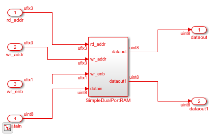
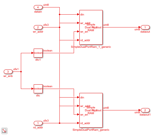
If you navigate the model, you see the Simple Dual Port RAM block.
open_system('SimpleDualPortRAM/SimpleDualPortRAM')
Input Arguments
Name-Value Arguments
Limitations
The importhdl function is not supported on Mac platforms.
Version History
Introduced in R2018b