Generate HDL Code for Simscape Models by Using Linearized Switch Approximation
This example shows how to generate HDL code for a Simscape™ model by using linearized switch approximation method.
Simscape Model with Linearized Switch Approximation
In this example, you learn how you can use the linearized switch approximation method to convert the Simscape™ three-phase permanent magnet synchronous motor (PMSM) model to an HDL implementation model for HDL code generation and synthesis. First, you replace the ideal insulated-gate bipolar transistor IGBT (Ideal, Switching) (Simscape Electrical) with linearized equivalents and generate an HDL implementation model by using the Simscape HDL Workflow Advisor. Then, for this implementation model, you generate the HDL code and synthesize the results by using the guided steps in the HDL Workflow Advisor. For more information, see HDL Workflow Advisor Tasks. You can then deploy the generated HDL code onto a Speedgoat® FPGA I/O module.
The linearized switch approximation method supports all local solvers. The three-phase inverter is modelled using linearized switch approximation method. The linearized switch approximation method provides an improved FPGA sample rate, reduced resource utilization, and dead time stability, and prevents validation errors. For more information on validation errors, see Troubleshoot Validation Errors in Simscape Hardware-in-the-Loop Workflow.
Set Up Synthesis Tool Path
To synthesize the generated HDL code, set up your synthesis tool path before you use HDL Coder™ to generate code. For example, if your synthesis tool is Xilinx® Vivado®, install the latest version of Xilinx Vivado as listed in HDL Language Support and Supported Third-Party Tools and Hardware.
Then, set the tool path to the installed Xilinx Vivado executable by using the hdlsetuptoolpath function:
hdlsetuptoolpath('ToolName','Xilinx Vivado','ToolPath','C:\Xilinx\Vivado\2020.2\bin\vivado.bat')
Three-Phase PMSM Drive
The model used in this example contains a three-phase PMSM in wye-wound configuration and a three-phase inverter. This model uses field-oriented control (FOC) to control the speed of the three-phase PMSM. The PMSM is a nonlinear block in the model. The inverter is connected to the battery. The Three-phase inverter subsystem has the switching elements as IGBTs. This model uses the Partitioning solver as a local solver.
Open the model at the MATLAB® command prompt.
ModelName = 'sschdlexThreePhasePMSMDrive';
open_system(ModelName)

To see the waveforms, simulate the model.
sim(ModelName)
open_system([ModelName '/Scope'])

PMSM Model Modified for Linearized Switch Approximation
You can modify this model for linearized switch approximation by replacing the switches (IGBTs) with linearized equivalents. To modify the model, double-click the Three-phase inverter subsystem and replace each IGBT with a subsystem containing an IGBT and a protection diode. The SimscapeFPGAHIL_lib library has the IGBTs and diodes compatible for HDL code generation (Simscape HIL simulation). You can open the library from MATLAB command window. To open this library, enter:
SimscapeFPGAHIL_lib
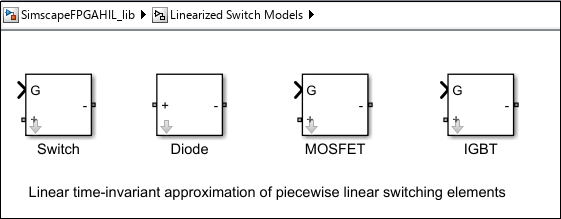
The library window contains the Linearized Switch Models subsystem. This subsystem contains linear time-invariant (LTI) approximations of the piecewise linear switching elements. Drag the IGBT block and the Diode block into the Three-phase inverter subsystem of your PMSM model and create a subsystem for each IGBT block and name the subsystems as IGBT+Diode.
The IGBT block consists of a resistor and a controlled current source. Double-click the IGBT block in the IGBT+Diode1 subsystem to update the values of its parameters. The Conductance (Gs) is the conductance of the resistor in Linearized Switch Models.  is different from the off-state conductance (
 ) of an IGBT when it is used for switching applications. The Time scaling
  scales the speed of the switching device response with respect to time. For the IGBT block,
Set Forward Voltage (V) to 0.8.
Set Threshold Voltage (V) to 0.5.
Set Conductance (1/Ohm)
to 4.4526.Set Time scaling
to 2.8994.Set Discrete sample time (s)
 to 2e-06.
Then, double-click the Diode block in the IGBT+Diode subsystem to update the different parameter values. For the Diode block,
Set Forward Voltage (V) to 0.8.
Set Conductance (1/Ohm)
to 4.4526.Set Time scaling
to 2.8994.Set Discrete sample time (s)
to 2e-06.
Similarly, update the parameter values for the other IGBT+Diode subsystems. For this example, the values of and are calibrated to 4.4526 and 2.8994, respectively, by using the Parameter Estimator app. If you have a license for Simulink® Design Optimization™ toolbox, you can use the Parameter Estimator app to tune the parameter values. You can also calibrate these values manually.
To open the model modified in this way, at the MATLAB command prompt, enter:
ModelNameLSA = 'sschdlexPMSMLinearizedSwitches';
open_system(ModelNameLSA)

To see the modified subsystem, enter:
open_system([ModelNameLSA,'/Three-phase inverter'])

When you simulate this model, the results of this model and the original Simscape model are same. To see how the model works, simulate the model.
sim(ModelNameLSA)
open_system([ModelNameLSA '/Scope'])

Generate HDL Implementation Model
The Simscape HDL Workflow Advisor converts the Simscape plant model to an HDL-compatible implementation model from which you generate HDL code. To generate the HDL implementation model:
1. Open the Simscape HDL Workflow Advisor.
sschdladvisor('sschdlexPMSMLinearizedSwitches')
2. In the Implementation model generation task folder, right-click the Generate implementation model task, then select Run to Selected Task. To get better resource utilization, in the Generate implementation model task window, set Map state space parameter to RAM to On.
After the task passes, you see a link to the HDL implementation model gmStateSpaceHDL_sschdlexPMSMLinearizedSwitc.
Generate HDL Code from Implementation Model
To modify the configuration parameter values for HDL code generation, enter this command at the MATLAB command prompt.
hdlsetup('gmStateSpaceHDL_sschdlexPMSMLinearizedSwitc')
Open HDL Workflow Advisor
The HDL Workflow Advisor guides you through the tasks required for generating HDL code and an FPGA design process. It provides you with feedback on the results of each task. When you complete the tasks, you have a synthesis result report from one of the supported synthesis tools.
To open the subsystem HDL Subsystem in the HDL implementation model into the HDL Workflow Advisor, enter this command at the MATLAB command prompt.
hdladvisor('gmStateSpaceHDL_sschdlexPMSMLinearizedSwitc/HDL Subsystem')
You can also open the HDL Workflow Advisor from your model window. Right-click the subsystem HDL Subsystem and select HDL Workflow Advisor from the list.
Set Target Device and Synthesis Tool
Before you generate HDL code, if you want to deploy the code onto a target platform, specify the synthesis tool.
Open the HDL Workflow Advisor.
Under the Set Target task folder, in the Set Target Device and Synthesis Tool task, specify Target workflow as
Generic ASIC/FPGAand Synthesis tool asXilinx Vivado. The rest of the fields are auto-populated. Specify the Family asKintex7, Device asxc7k325t, Package asfbg676, and Speed as -1.In the Set Target Frequency task, specify the Target Frequency as 200.
Select the task that you want to run and click Run This Task.
Generate HDL Code
In the HDL Code Generation task folder, select Set HDL Options, then click the HDL Code Generation Settings button to open the Configuration Parameters dialog box. Select
Adaptive pipeliningunder HDL Code Generation > Optimizations > Pipelining. Click Apply.Under the HDL Code Generation > Global Settings > Clock Settings section, set the
Oversampling factorto 273. Click Apply, then click OK. To generate HDL code, run the tasks under the HDL Code Generation task folder.
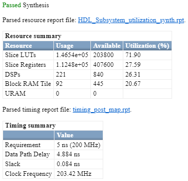
Synthesize Generated HDL Code
HDL Coder synthesizes the HDL code on the target platform and generates area and timing reports for your design based on the target device that you specify. You can run logic synthesis for a specified FPGA device and get the synthesis reports.
In the FPGA Synthesis and Analysis task folder:
Create an FPGA synthesis project for your supported FPGA synthesis tool.
Start supported FPGA synthesis tools to perform synthesis, mapping, and place/route tasks. To run FPGA synthesis, right-click the Run Synthesis task under the Perform Synthesis and P/R subtask folder. This starts Xilinx Vivado and executes the Vivado Synthesis step. You can annotate your original model with critical path information obtained from the synthesis tools.
Deploy Three-Phase PMSM Drive to Speedgoat FPGA I/O Modules
In the HDL implementation model, the HDL Subsystem contains blocks you run on the FPGA. You can run the HDL Workflow Advisor on this subsystem to deploy the HDL algorithm onto FPGA boards in Speedgoat target computers. For an example, see Hardware-in-the-Loop Implementation of Simscape Model on Speedgoat FPGA I/O Modules.
References
[1] Pejovic, P., and D. Maksimovic. “A Method for Fast Time-Domain Simulation of Networks with Switches.” IEEE Transactions on Power Electronics 9, no. 4 (July 1994): 449–56, https://doi.org/10.1109/63.318904.
See Also
Functions
Related Topics
- Generate HDL Code for Simscape Models
- Hardware-in-the-Loop Implementation of Simscape Model on Speedgoat FPGA I/O Modules
- Generate HDL Code for Nonlinear Simscape Models by Using Partitioning Solver
- Generate HDL Code for Simscape Models by Using Trapezoidal Rule Solver
- Generate HDL Code for Simscape Three-Phase PMSM Drive Containing Averaged Switch
- Deploy Simscape DC Motor Model to Speedgoat FPGA IO Module
You can also select a web site from the following list:
Americas
- América Latina (Español)
- Canada (English)
- United States (English)
Europe
- Belgium (English)
- Denmark (English)
- Deutschland (Deutsch)
- España (Español)
- Finland (English)
- France (Français)
- Ireland (English)
- Italia (Italiano)
- Luxembourg (English)
- Netherlands (English)
- Norway (English)
- Österreich (Deutsch)
- Portugal (English)
- Sweden (English)
- Switzerland
- United Kingdom (English)