Use Sample-Based Inputs and Frame-Based Inputs in an Algorithm
You can use matrix or frame-based signals with scalar or sample-based signals in the same algorithm when you use the frame-to-sample conversion operation. You can use non-streamed scalar inputs with streamed frame inputs to generate synthesizable HDL code for algorithms where you apply a threshold value or gain to an incoming streamed signal. This example uses an RGB image as an input and applies a color filter based on the threshold signals.
Model Frame Input and Sample Input Interaction
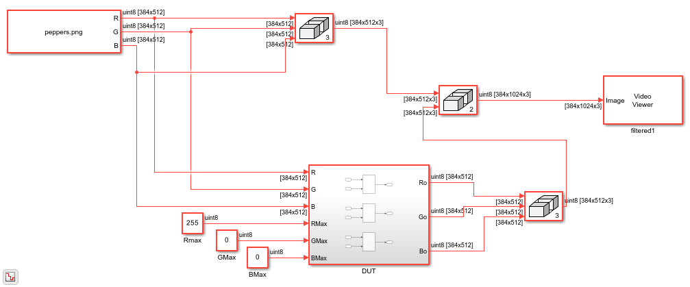
This example takes an RGB input image, splits the image into three individual RGB inputs signals, and applies a color filter on each signal based on the threshold signals specific to each color input. The threshold signals are inputs to the DUT as non-streamed scalar values.
open_system("hdlFrame_RGBFilter");
set_param('hdlFrame_RGBFilter', 'SimulationCommand', 'update');
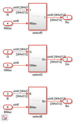
Open the DUT subsystem to see the blocks that perform the filtering operation on the RGB frame inputs.
open_system('hdlFrame_RGBFilter/DUT');
Run the Model
The model uses 2-D matrices as inputs to the DUT. These inputs signals are the separated R,G,B components of the input image. Each streamed-input signal is a frame input matrix composed of 384x512 pixels. Each non-streamed threshold input is a uint8 scalar value. Simulate the model to see the color-filtered output image.
sim("hdlFrame_RGBFilter");
Generate HDL Code
Generate synthesizable HDL code by using the frame-to-sample conversion. Set the HDL block property ConvertToSamples on the Inport blocks of the DUT that connect to the R, G, B input signals to convert the input signals from frame-based to sample-based inputs. You do not need to enable the ConvertToSamples property on the threshold inputs because they are scalar sample-based values.
hdlset_param('hdlFrame_RGBFilter/DUT/R', 'ConvertToSamples', 'on');
hdlset_param('hdlFrame_RGBFilter/DUT/G', 'ConvertToSamples', 'on');
hdlset_param('hdlFrame_RGBFilter/DUT/B', 'ConvertToSamples', 'on');
Enable the frame-to-sample conversion optimization and generate HDL code using the makehdl command. For more information on the frame-to-sample conversion optimization, see HDL Code Generation from Frame-Based Algorithms.
hdlset_param('hdlFrame_RGBFilter', 'FrameToSampleConversion', 'on')
makehdl('hdlFrame_RGBFilter/DUT')
The frame-to-sample conversion separates the frame-based inputs into sample, valid, and ready signals for a sample-based hardware-targeted interface.
Perform FPGA Synthesis and Analysis
In the HDL Workflow Advisor, perform FPGA synthesis using the generic ASIC/FPGA workflow. To generate HDL code and run synthesis on your design using the HDL Workflow Advisor, see HDL Code Generation and FPGA Synthesis from Simulink Model.
Use these settings located in the HDL Code Generation > Target pane in the Model Configuration Parameters dialog box:
Synthesis tool set to
Xilinx VivadoFamily set to
ZynqDevice set to
xc7z045Package set to
ffg900Speed set to
-2Target Frequency (MHz) set to
200
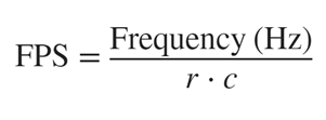
This table shows the synthesis results for the DUT subsystem in hdlFrame_RBGFilter. The results report the frames per seconds (FPS) for each individual RGB channel, which assumes that each RGB input is streamed independently of one another.

The synthesis results show a positive slack of 2.03 ns, which indicates that the timing constraints are met. The r and c columns correspond to the number of rows and columns of the frame, respectively. The FPSMax and FPSTgtFreq columns correspond to the average FPS at the output when using the maximum achievable frequency Fmax and the Target Frequency 200 MHz, respectively. To calculate the average FPS, use this equation:
See Also
Topics
- Generate IP Core for Frame-Based Model with AXI4 Stream Interfaces
- Use Neighborhood, Reduction, and Iterator Patterns with a Frame-Based Model or Function for HDL Code Generation
- Generate HDL Code from Frame-Based Models by Using Neighborhood Modeling Methods
- HDL Code Generation from Frame-Based Algorithms