Use Neighborhood, Reduction, and Iterator Patterns with a Frame-Based Model or Function for HDL Code Generation
In this example, you use frame-based modeling to model an image processing algorithm that rectifies fog in an image. You then generate synthesizable HDL code by using the HDL Coder™ frame-to-sample conversion optimization to generate pixel-based code from the frame-based model.
The fog rectification model uses neighborhood, reduction, and iterator patterns. You can model neighborhood patterns by using the hdl.npufun function in a MATLAB® Function block or the Neighborhood Processing Subsystem block. You can implement reduction and iterator patterns by using hdl.iteratorfun in a MATLAB Function block.
Additionally, as an alternative from generating HDL code from a Simulink® model, you can use a MATLAB function to generate HDL code that contains the frame-based fog rectification algorithm.
Model Algorithm by Using a MATLAB Function Block
In the hdlFrame_FogRectification_2D_MLFB model, the device under test (DUT) contains a MATLAB Function block that includes the neighborhood processing, reduction, and iterator operations needed for fog rectification. To generate synthesizable HDL code from the frame-based model, the neighborhood processing algorithm uses the frame-to-sample conversion supported function hdl.npufun. The iterator and reduction algorithms use the frame-to-sample conversion supported function hdl.iteratorfun. For more information, see hdl.npufun and hdl.iteratorfun. Using these two functions in a frame-based model enables you to contain an entire fog rectification algorithm in a single MATLAB Function block.
Open the hdlFrame_FogRectification_2D_MLFB/DUT/MATLAB Function subsystem to see the fog rectification algorithm.
load_system("hdlFrame_FogRectification_2D_MLFB");
open_system("hdlFrame_FogRectification_2D_MLFB/DUT/MATLAB Function");
function [r_out,g_out,b_out]  = fog_rectification(Ru, Gu, Bu)

[im_gray, restoreR, restoreG, restoreB] = fog_stage1(Ru, Gu, Bu);

[r_out,g_out,b_out] = fog_rectification_m(im_gray, restoreR, restoreG, restoreB);

end

function [im_gray, restoreR, restoreG, restoreB] = fog_stage1(Ru, Gu, Bu)
coder.inline('never')


%% Dark channel Estimation from input
darkChannel = hdl.npufun(@min_kernel, [1 1], Ru, Gu, Bu);

% diff_im is used as input and output variable for anisotropic diffusion
diff_im = fi(fi(0.9,0,16,14)*darkChannel, 1, 32, 16);

%% Refine dark channel using Anisotropic diffusion.
diff_im(:) = hdl.npufun(@filter_kernel, [3 3], diff_im);
diff_im(:) = hdl.npufun(@filter_kernel, [3 3], diff_im);
diff_im(:) = hdl.npufun(@filter_kernel, [3 3], diff_im);

%% Reduction with min
% diff_im = min(darkChannel,diff_im);
diff_im(:) = hdl.npufun(@min_kernel2, [1 1], darkChannel, diff_im);

diff_im(:) = cast(fi(0.6,0,16,14)*diff_im, 'like', diff_im);

%% Parallel element-wise math to compute
%  Restoration with inverse Koschmieder's law
factor = hdl.npufun(@calc_restoration_factor, [1 1], diff_im);

restoreRf = (Ru-diff_im).*factor;
restoreGf = (Gu-diff_im).*factor;
restoreBf = (Bu-diff_im).*factor;

% Convert to integer
restoreR = uint8(restoreRf);
restoreG = uint8(restoreGf);
restoreB = uint8(restoreBf);

%%
% Stretching performs the histogram stretching of the image.
% im is the input color image and p is cdf limit.
% out is the contrast stretched image and cdf is the cumulative prob.
% density function and T is the stretching function.
% RGB to grayscale conversion
im_gray = hdl.npufun(@convert_gray, [1 1], restoreR, restoreG, restoreB);

% [restoreR, restoreG, restoreB] = hdl.npufun(@zero_to_one, [1 1], restoreR, restoreG, restoreB);
% restoreR(restoreR == 0) = 1;
% restoreG(restoreG == 0) = 1;
% restoreB(restoreB == 0) = 1;

% Rewriting 0-1 setting to avoid reshape
zeros_to_one = (restoreR == 0);
restoreR = restoreR + uint8(zeros_to_one);
zeros_to_one = (restoreG == 0);
restoreG = restoreG + uint8(zeros_to_one);
zeros_to_one = (restoreB == 0);
restoreB = restoreB + uint8(zeros_to_one);

end

function out = filter_kernel(in)
hN = fi([0.0625 0.1250 0.0625; 0.1250 0.2500 0.1250; 0.0625 0.1250 0.0625], 0, 16, 15);
out = cast(sum(in(:).*hN(:)),'like',in);
end

function out = min_kernel(R, G, B)
    out = min([R, G, B]);
end

function out = convert_gray(R, G, B)

out = uint8(round(fi(0.2989,1,16,15) * R + fi(0.5870,1,16,15) * G + fi(0.1140,1,16,15) * B));

end

function out = min_kernel2(A, B)
    out = min(A, B);
end

function factor = calc_restoration_factor(diff_im)

ds = bitshift(diff_im, -8); % divide by 256 to make value < 1
% compute factor with taylor series expansion
% 1/(1-x) = 1 + x + x^2 + x^3 + x^4 + x^5;
ds2 = fi(ds*ds,1,32,16);
ds3 = fi(ds2*ds,1,32,16);
ds4 = fi(ds3*ds,1,32,16);
ds5 = fi(ds4*ds,1,32,16);
factor = fi(1 + ds + ds2 + ds3 + ds4 + ds5,1,32,24);

end

function [r_out,g_out,b_out] = fog_rectification_m(im_gray, r, g, b)

coder.inline('never')
%FOG_RECTIFICATION_HDL_3_STAGE2
% histogram computation
% Find cdf
% Find breakpoints of table
% Compute table
% Use table on input image to create output image

% histogram calculation
hist = zeros(1, 256, 'uint32');
hist = hdl.iteratorfun(@hist_kernel_fcn, im_gray, hist);

cdf_init = zeros(256,1,'uint32');
cdf = hdl.iteratorfun(@cdf_compute, hist, cdf_init);

N = numel(im_gray);
p1 = fi(5*N/100);
p2 = fi(N-(5*N/100));

i1i2 = zeros(1,2,'uint8');
i1i2 = hdl.iteratorfun(@find_break_points, cdf, i1i2, p1, p2);
i1 = i1i2(1);
i2 = 255-i1i2(2);

o1 = fi(255*0.10,1,32,16,'RoundingMethod','Zero','OverflowAction','Saturate');
o2 = fi(255*0.90,1,32,16,'RoundingMethod','Zero','OverflowAction','Saturate');

t1 = o1/fi(i1,'RoundingMethod','Zero','OverflowAction','Saturate');
t2 = (o2-o1)/fi(i2-i1,'RoundingMethod','Zero','OverflowAction','Saturate');
t3 = (255-o2)/fi(255-i2,'RoundingMethod','Zero','OverflowAction','Saturate');

t1f = fi(t1, 0, 32, 24);
t2f = fi(t2, 0, 32, 24);
t3f = fi(t3, 0, 32, 24);

T = zeros(1,256, 'uint8');
T = hdl.iteratorfun(@createTable, T, T, i1, i2, t1f, t2f, t3f, o1, o2);

[r_out, g_out, b_out] = hdl.npufun(@table_lookup, [1,1], r, g, b, 'KernelArg', T);

end

function count = hist_kernel_fcn(pix, count, idx) %#ok<*INUSD>

count(pix+1) = count(pix+1) +1;

end

function cdf = cdf_compute(hist, cdf, idx)

if idx > 1
    cdf(idx) = cdf(idx-cast(1,'like',idx)) + hist;
else
    cdf(1) = hist;
end

end

function i1i2 = find_break_points(cdf, i1i2, idx, p1, p2)
    if (cdf <= p1)
        i1i2(1) = i1i2(1) + 1;
    end

    if (cdf >= p2)
        i1i2(2) = i1i2(2) + 1;
    end
end

function T = createTable(unused, T, idx, i1, i2, t1f, t2f, t3f, o1, o2)

    is = uint16(idx);
    if is <= i1+1
        T(idx) = uint8(t1f*(is-1));
    elseif is >= i1+2 && is <= i2+1
        T(idx) = uint8(((t2f)*(is-1))-((t2f)*i1)+o1);
    else
        T(idx) = uint8(((t3f)*(is-1))-((t3f)*i2)+o2);
    end

end

function [r_out, g_out, b_out] = table_lookup(r, g, b, T)
    out1=T(r);
    out2=T(g);
    out3=T(b);

    r_out = uint8(out1);
    g_out = uint8(out2);
    b_out = uint8(out3);
end
Run the Model
The model uses 2-D matrices as inputs to the DUT. These inputs signals are the separated R, G, and B components of the input image. Each input signal is a frame input matrix composed of 240x320 pixels. Simulate the model to see the frame size and simulation results.
sim("hdlFrame_FogRectification_2D_MLFB");
Generate HDL Code
Generate synthesizable HDL code by using the frame-to-sample conversion. Set the HDL block property ConvertToSamples on the Inport blocks of the DUT that connect to the R, G, B input signals to convert the input signals from frame-based to sample-based inputs.
hdlset_param('hdlFrame_FogRectification_2D_MLFB/DUT/r_in', 'ConvertToSamples', 'on');
hdlset_param('hdlFrame_FogRectification_2D_MLFB/DUT/g_in', 'ConvertToSamples', 'on');
hdlset_param('hdlFrame_FogRectification_2D_MLFB/DUT/b_in', 'ConvertToSamples', 'on');
For the MATLAB Function block that contains the fog rectification algorithm, set the HDL block property Architecture to MATLAB Datapath. Enable the frame-to-sample conversion optimization and generate HDL code using the makehdl command. For more information on the frame-to-sample conversion optimization, see HDL Code Generation from Frame-Based Algorithms.
hdlset_param('hdlFrame_FogRectification_2D_MLFB/DUT/MATLAB Function', 'Architecture', 'MATLAB Datapath')
hdlset_param('hdlFrame_FogRectification_2D_MLFB', 'FrameToSampleConversion', 'on')
makehdl('hdlFrame_FogRectification_2D_MLFB/DUT')
The frame-to-sample conversion separates the frame-based inputs into sample, valid, and ready signals for a sample-based hardware-targeted interface.
Model Algorithm by Using Neighborhood Processing Subsystem and MATLAB Function Blocks
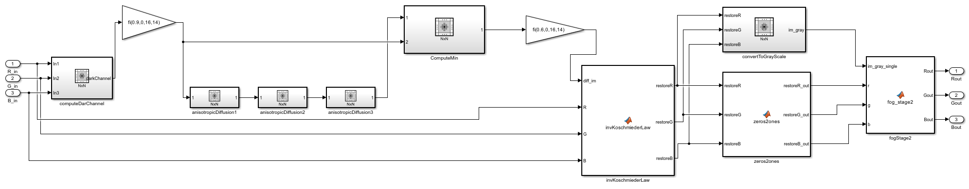
In the hdlFrame_FogRectification_2D_SLBlock model, the DUT models the fog rectification algorithm using multiple Neighborhood Processing Subsystem and MATLAB Function blocks that use the hdl.npufun function. The MATLAB Function block fogStage2 and the hdl.iteratorfun function model the reduction and iterator functions. Separating the fog rectification algorithm into various Simulink blocks enables you to visualize and model the different aspects of the fog rectification in a more modular way than with a single MATLAB Function block.
Open the hdlFrame_FogRectification_2D_SLBlock/DUT subsystem to see the fog rectification algorithm.
load_system("hdlFrame_FogRectification_2D_SLBlock");
open_system("hdlFrame_FogRectification_2D_SLBlock/DUT");
Run the Model
The model uses 2-D matrices as inputs to the DUT. These inputs signals are the separated R, G, and B components of the input image. Each input signal is a frame input matrix composed of 240x320 pixels. Simulate the model to see the frame size and simulation results.
sim("hdlFrame_FogRectification_2D_SLBlock");
Although the hdlFrame_FogRectification_2D_SLBlock and hdlFrame_FogRectification_2D_MLFB models differ in design, the output is the same. Both models can also generate synthesizable HDL code for sample-based hardware.
Generate HDL Code
Generate synthesizable HDL code by using the frame-to-sample conversion. Set the HDL block property ConvertToSamples on the Inport blocks of the DUT that connect to the R, G, B input signals to convert the input signals from frame-based to sample-based inputs.
hdlset_param('hdlFrame_FogRectification_2D_SLBlock/DUT/R_in', 'ConvertToSamples', 'on');
hdlset_param('hdlFrame_FogRectification_2D_SLBlock/DUT/G_in', 'ConvertToSamples', 'on');
hdlset_param('hdlFrame_FogRectification_2D_SLBlock/DUT/B_in', 'ConvertToSamples', 'on');
Enable the frame-to-sample conversion optimization and generate HDL code using the makehdl command.
hdlset_param('hdlFrame_FogRectification_2D_SLBlock', 'FrameToSampleConversion', 'on')
makehdl('hdlFrame_FogRectification_2D_SLBlock/DUT')
The frame-to-sample conversion separates the frame-based inputs into sample, valid, and ready signals for a sample-based hardware-targeted interface.
Model Algorithm and Generate HDL Code by Using a MATLAB Function
You can also generate HDL code directly from MATLAB functions by using the MATLAB-to-HDL workflow. For more information on the MATLAB-to-HDL workflow, see Programmatically Generate, Verify, and Synthesize HDL Code from MATLAB Code. In this example, the MATLAB function fog_rectification contains the MATLAB code from the MATLAB Function block in the hdlFrame_FogRectification_2D_MLFB/DUT subsystem.
open("fog_rectification");
Open the test bench function, fog_rectification_tb, to see the input fog rectification image separated into the R,G, and B components.
open("fog_rectification_tb");
The fog_rectification_tb script tests the function by inputting the original fog rectification image and splitting the input signal into the R, G, and B frame-based components of the image.
The test bench uses code generation to run the algorithm faster. To specify the input types and generate HDL code quickly without running the test bench, use the -args option.
To generate HDL code from a MATLAB function, create a coder.HdlConfig object, hdlcfg. Set the DesignFunctionName property to the fog_rectification function.
hdlcfg = coder.config('hdl');
hdlcfg.DesignFunctionName = 'fog_rectification';
Enable frame-to-sample conversion for the coder.HdlConfig object.
hdlcfg.FrameToSampleConversion = true;
Specify the input image and separate the image into its R, G, and B frame-based input components.
I = imread('inputFogRectification.png');
R = I(:,:,1);
G = I(:,:,2);
B = I(:,:,3);
Generate HDL code by using the codegen function. Specify the input arguments in the codegen command by using the -args option.
codegen -config hdlcfg -args { R,G,B }