Testing with an HDL Test Bench
Workflow for Testing with an HDL Test Bench
Generating the Filter and Test Bench HDL Code
Use the Filter Design HDL Coder™ UI or command-line interface to generate the HDL code for your filter design and test bench. The UI generates a VHDL® or Verilog test bench file, depending on your language selection for the generated HDL code. You can specify a different test bench language by selecting the Test bench language option in the Test Bench pane of the Generate HDL tool. You cannot specify a different test bench language when using the command-line interface.
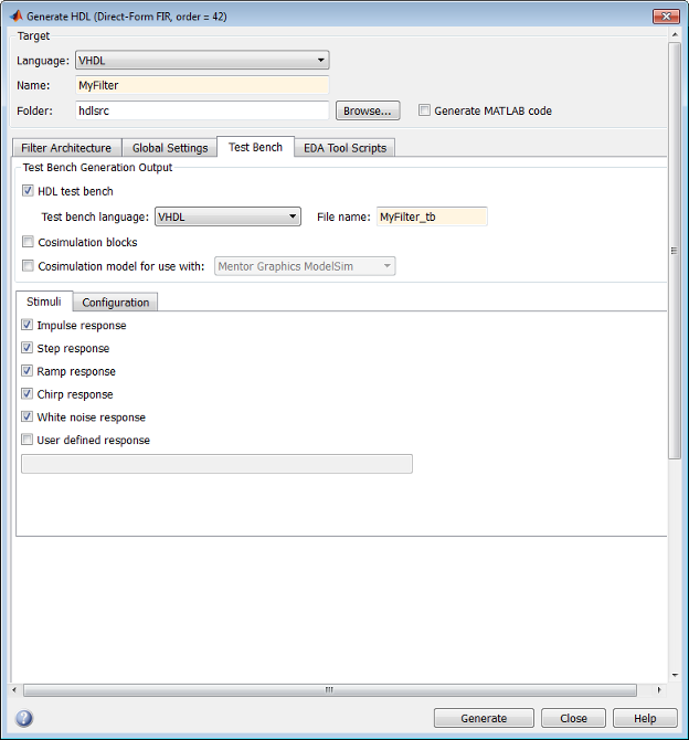
This figure shows settings for generating the filter (VHDL) and test bench (Verilog) files MyFilter.vhd,
and MyFilter_tb.v. The tool also specifies the location for
the generated files, in this case, the folder hdlsrc under
the current working folder.

After you click Generate, the coder displays progress information similar to the following in the MATLAB® Command Window:
### Starting VHDL code generation process for filter: MyFilter
### Generating: C:\Work\sl_hdlcoder_work\hdlsrc\MyFilter.vhd
### Starting generation of MyFilter VHDL entity
### Starting generation of MyFilter VHDL architecture
### HDL latency is 2 samples
### Successful completion of VHDL code generation process for filter: MyFilter

### Starting generation of VERILOG Test Bench
### Generating input stimulus
### Done generating input stimulus; length 3429 samples.
### Generating Test bench: C:\Work\sl_hdlcoder_work\hdlsrc\MyFilter_tb.v
### Please wait ...
### Done generating VERILOG Test Bench
Note
The length of the input stimulus samples varies from filter to filter. For
example, the value 3429 in the preceding message sequence
is not fixed; the value depends on the filter under test.
If you call the generatehdl function from the
command-line interface, set code and test bench generation options with property
name and value pairs. You can also use the function generatetbstimulus to return
the test bench stimulus to a workspace variable.
Starting the Simulator
After you generate your filter and test bench HDL files, start your simulator. When you start the Siemens® ModelSim™ simulator, a screen display similar to this appears:

After starting the simulator, set the current folder to the folder that contains your generated HDL files.
Compiling the Generated Filter and Test Bench Files
Using your choice of HDL compiler, compile the generated filter and test bench HDL files. Depending on the language of the generated test bench and the simulator you are using, you may have to complete some precompilation setup. For example, in the Siemens ModelSim simulator, you might choose to create a design library to store compiled VHDL entities, packages, architectures, and configurations.
This Siemens
ModelSim command sequence changes the current folder to
hdlsrc, creates the design library
work, and compiles VHDL filter and filter test bench code. The vlib
command creates the design library work and the vcom commands
initiate the compilations.
cd hdlsrc
vlib work
vcom MyFilter.vhd
vcom MyFilter_tb.vhd
Note
For VHDL test bench code that has floating-point (double) realizations,
use a compiler that supports VHDL-93 or VHDL-02. For example, in the
Siemens
ModelSim simulator, specify the vcom command with
the -93 option. Do not compile the generated test bench
code with a VHDL-87 compiler. VHDL test benches using double-precision data types do not support
VHDL-87. The test bench code uses the image attribute, which is available
only in VHDL-93 or higher.
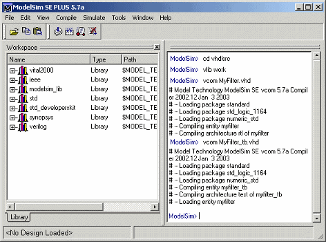
This figure shows this command sequence and informational messages displayed during compilation.

Running the Test Bench Simulation
Once your generated HDL files are compiled, load and run the test bench. The
procedure varies depending on the simulator you are using. In the
Siemens
ModelSim simulator, you load the test bench for simulation with the
vsim command. For example:
vsim work.MyFilter_tb
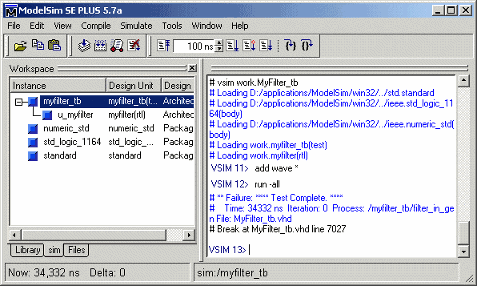
This figure shows the results of loading work.MyFilter_tb
with the vsim command.

Once the design is loaded into the simulator, consider opening a display
window for monitoring the simulation as the test bench runs. For example, in the
Siemens
ModelSim simulator, you can use the add wave * command
to open a wave window to view the results of the simulation
as HDL waveforms.
To start running the simulation, issue the start simulator command. For
example, in the Siemens
ModelSim simulator, you can start a simulation with the run
-all command.
This figure shows the add wave * command being used to open
a wave window and the -run
all command being used to start a
simulation.

As your test bench simulation runs, watch for error messages. If error messages appear, interpret them as they pertain to your filter design and the code generation options you applied. For example, some HDL optimization options can produce numeric results that differ from the results produced by the original filter object. For HDL test benches, expected and actual results are compared. If they differ (excluding the specified error margin), an error message similar to this is returned:
Error in filter test: Expected xxxxxxxx Actual xxxxxxxx
You must determine whether the actual results are expected based on the customizations you specified when generating the filter HDL code.
Note
The failure message that appears in the preceding display is not flagging
an error. If the message includes the text Test Complete,
the test bench has run to completion without encountering an error. The
Failure part of the message is tied to the mechanism
the coder uses to end the simulation.
This wave window shows the simulation results as HDL waveforms.

Enabling Test Bench Generation
To enable generation of an HDL test bench:
Select the Test Bench pane in the Generate HDL tool.
Select the HDL test bench option, as shown in this figure.

Click Generate to generate HDL and test bench code.
Tip
By default, HDL test bench is selected.
Command-Line Alternative: Use the generatehdl function with the
property GenerateHDLTestBench to generate an HDL test bench.
Renaming the Test Bench
The coder derives the name of the test bench file by appending the postfix
_tb to the name of the quantized filter object. The file type
extension depends on the type of test bench that is being generated.
| If the Test Bench Is a... | The Extension Is... |
|---|---|
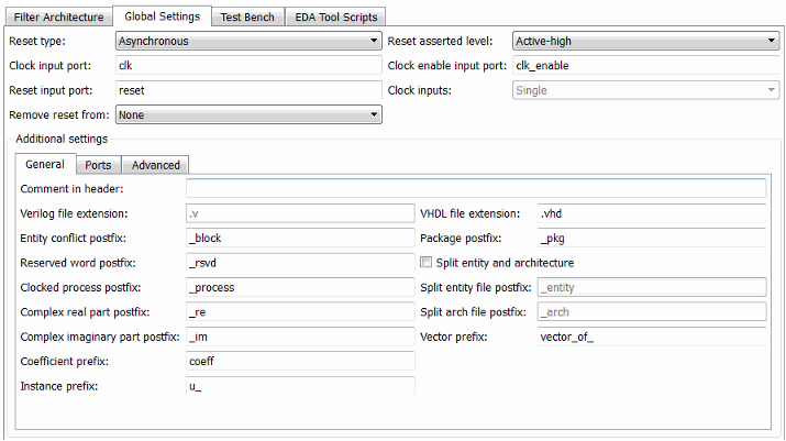
| Verilog file | Defined by the Verilog file extension field in the General subpane of the Global Settings pane of the Generate HDL tool |
| VHDL file | Defined by the VHDL file extension field in the Global Settings pane of the Generate HDL tool |
The file is placed in the folder defined by the Folder option in the Target pane of the Generate HDL tool.
To specify a test bench name, enter the name in the Name field of the Test bench settings pane, as shown in this figure.

Note
If you enter a character vector that is a VHDL or Verilog reserved word, the coder corrects the identifier by appending the reserved word postfix to the character vector.
Command-Line Alternative: Use the generatehdl property TestBenchName to
specify a name for your test bench.
Splitting Test Bench Code and Data into Separate Files
By default, the coder generates a single test bench file, containing test bench helper functions, data, and test bench code. You can split these elements into separate files by selecting the Multi-file test bench option in the Configuration subpane of the Test Bench pane of the Generate HDL tool.

When you select the Multi-file test bench option, the
Test bench data file name postfix option is enabled. The
test bench file names are then derived from the name of the test bench and the
postfix setting,
TestBenchName_TestBenchDataPostfix.
For example, if the test bench name is my_fir_filt, and the
target language is VHDL, the default test bench file names are:
my_fir_filt_tb.vhd: test bench codemy_fir_filt_tb_pkg.vhd: helper functions packagemy_fir_filt_tb_data.vhd: data package
If the filter name is my_fir_filt and the target
language is Verilog, the default test bench file names are:
my_fir_filt_tb.v: test bench codemy_fir_filt_tb_pkg.v: helper functions packagemy_fir_filt_tb_data.v: test bench data
Command-Line Alternative: Use the generatehdl properties MultifileTestBench, TestBenchDataPostfix, and TestBenchName to
generate and name separate test bench helper functions, data, and test bench code
files.
Configuring the Clock
Based on default settings, the coder configures the clock for a filter test bench such that it:
Forces clock enable input signals to active high (1).
Asserts the clock enable signal 1 clock cycle after deassertion of the reset signal.
Forces clock input signals low (0) for a duration of 5 nanoseconds and high (1) for a duration of 5 nanoseconds.
To change these clock configuration settings:
Click Configuration in the Test bench pane of the Generate HDL tool.
Within the Test Bench pane, select the Configuration subpane.
Make the configuration changes shown in the table.
If You Want to... Then... Disable the forcing of clock enable input signals Clear Force clock enable. Disable the forcing of clock input signals Clear Force clock. Reset the number of nanoseconds that the test bench drives the clock input signals low (0) Specify a positive integer or double (with a maximum of 6 significant digits after the decimal point) in the Clock low time field. Reset the number of nanoseconds that the test bench drives the clock input signals high (1) Specify a positive integer or double (with a maximum of 6 significant digits after the decimal point) in the Clock high time field. Change the delay time elapsed between the deassertion of the reset signal and the assertion of clock enable signal. Specify a positive integer in the Clock enable delay field. This figure highlights the applicable options.

Command-Line Alternative: Use the generatehdl properties ForceClock, ClockHighTime,
ForceClockEnable, and TestBenchClockEnableDelay to reconfigure the test bench
clock.
Configuring Resets
Based on default settings, the coder configures the reset for a filter test bench such that it:
Forces reset input signals to active high (1). (Set the test bench reset input levels with the Reset asserted level option).
Asserts reset input signals for a duration of 2 clock cycles.
Applies a hold time of 2 nanoseconds for reset input signals.
Hold time is the amount of time the test bench holds the reset input signals past the clock rising edge. The figure shows the application of a hold time (thold) for reset input signals in the active high and active low cases. The test bench asserts reset after some initial clock cycles defined by the Reset length option. The default Reset length of 2 clock cycles is shown.

Note
The hold time applies to reset input signals only if the forcing of reset input signals is enabled.
The table summarizes the reset configuration settings.
| If You Want to... | Then... |
|---|---|
| Disable the forcing of reset input signals | Clear Force reset in the Test Bench pane of the Generate HDL tool. |
| Change the length of time (in clock cycles) during which reset is asserted | Set Reset length (in clock cycles) to an integer greater than or equal to 0. This option is located in the Test Bench pane of the Generate HDL tool. |
| Change the reset value to active low (0) | Select Active-low from the
Reset asserted level menu in the
Global Settings pane of the Generate HDL
tool (see Setting the Asserted Level for the Reset Input Signal) |
| Set the hold time | Specify a positive integer or double (with a maximum of 6
significant digits after the decimal point), representing
nanoseconds, in the Hold time field. When the
Hold time changes, the Setup time
(ns) value is updated. The Setup time
(ns) value computed as (clock period -
HoldTime) in nanoseconds. These options are in the
Test Bench pane of the Generate HDL
tool. |
These figures highlight the applicable options.


Note
The hold time and setup time settings also apply to data input signals.
Command-Line Alternative: Use the generatehdl properties ForceReset, ResetLength, and
HoldTime to reconfigure
test bench resets.
Setting a Hold Time for Data Input Signals
By default, the coder applies a hold time of 2 nanoseconds for filter data input signals. The hold time is the amount of time that data input signals are to be held past the clock rising edge. This figure shows the application of a hold time (thold) for data input signals.

To change the hold time setting,
Click the Test Bench tab in the Generate HDL tool.
Within the Test Bench pane, select the Configuration subpane.
Specify a positive integer or double (with a maximum of 6 significant digits after the decimal point), representing nanoseconds, in the Hold time field. In this figure, the hold time is set to 2 nanoseconds.
When the Hold time changes, the Setup time (ns) value updates. The coder computes the Setup time (ns) value as
(clock period -
                                    HoldTime)
in nanoseconds. Setup time (ns) is a display-only field.
Note
When you enable forcing of reset input signals, the hold time and setup time settings also apply to the reset signals.
Command-Line Alternative: Use the generatehdl property HoldTime to adjust the
hold time setting.
Setting an Error Margin for Optimized Filter Code
Customizations that provide optimizations can generate test bench code that produces numeric results that differ from results produced by the original filter object. These options include:
Optimize for HDL
FIR adder style set to
TreeAdd pipeline registers for FIR, asymmetric FIR, and symmetric FIR filters
To account for differences in numeric results, consider setting an error margin for the generated test bench. The error margin is the number of least significant bits the test bench ignores when comparing the results. The Error margin (bits) parameter appears only if you select filter optimizations that can affect the numeric results. To set an error margin:
Select the Test Bench pane in the Generate HDL tool.
Within the Test Bench pane, select the Configuration subpane.
For fixed-point filters, the initial Error margin (bits) field has a default value of
4. To change the error margin, enter an integer in the Error margin (bits) field. In this figure, the error margin is set to4bits.
Command-Line Alternative: Use the generatehdl property ErrorMargin to
specify the number of bits of tolerable error.
Setting an Initial Value for Test Bench Inputs
By default, the initial value driven on test bench inputs is
'X' (unknown). Alternatively, you can specify that the
initial value driven on test bench inputs is 0, as
follows:
Select the Test Bench pane in the Generate HDL tool.
Within the Test Bench pane, select the Configuration subpane.

To set an initial test bench input value of
0, select the Initialize test bench inputs option.To set an initial test bench input value of
'X', clear the Initialize test bench inputs option.
Command-Line Alternative: Use the generatehdl property InitializeTestBenchInputs to set the initial test bench input
value.
Setting Test Bench Stimuli
By default, the coder generates a filter test bench that includes stimuli that correspond to the given filter type. However, you can adjust the stimuli settings or specify user-defined stimuli, if desired.
To modify the stimuli included in a test bench, select one or more response types on the Stimuli subpane of the Test bench tab of the Generate HDL tool. The figure highlights this pane of the tool.

If you select User defined response, specify an expression or function that returns a vector of values to be applied to the filter. The values specified in the vector are quantized and scaled based on the quantization settings of the filter.
Command-Line Alternative: Use the generatehdl properties TestBenchStimulus and TestBenchUserStimulus to adjust stimuli settings.
Setting a Postfix for Reference Signal Names
Reference signal data is represented as arrays in the generated test bench code.
The character vector specified by Test bench reference postfix
is appended to the generated signal names. The default is
'_ref'.
You can set the postfix to a value other than '_ref'. To change
this parameter:
Select the Test Bench pane in the Generate HDL tool.
Within the Test Bench pane, select the Configuration subpane.
Enter a new character vector in the Test bench reference postfix field, as shown in this figure.

Command-Line Alternative: Use the generatehdl property TestBenchReferencePostfix to change the postfix character
vector.
