Ethernet AXI Manager
Note
Ethernet AXI master has been renamed to Ethernet AXI manager and the UDP MATLAB® as AXI Master IP has been renamed to the UDP AXI Manager IP. In the software and documentation, the terms "manager" and "subordinate" replace "master" and "slave," respectively.
Integrate and configure AXI manager over Ethernet using user datagram protocol (UDP) for Intel® devices. To use Ethernet AXI manager, you must first include these two intellectual property (IP) blocks in your project: Ethernet media access controller (MAC) Hub and UDP AXI Manager.
Ethernet MAC Hub IP
The Ethernet MAC Hub HDL IP supports the gigabit media independent interface (GMII). This Ethernet MAC Hub IP connects the Ethernet physical layer (PHY) to the UDP AXI Manager IP.
Interface of Ethernet MAC Hub IP
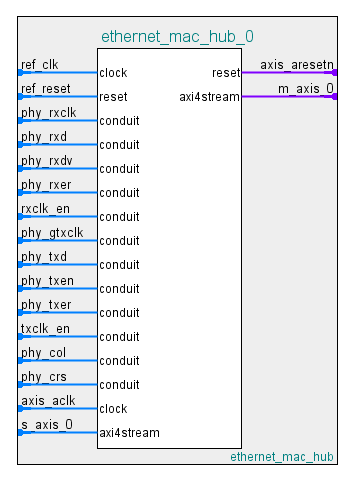
The interface of the Ethernet MAC Hub IP includes the ports in this table.
| Port | Description |
|---|---|
| s_axis_0 | AXI-stream subordinate interface. Connect this port to the m_axis port on the UDP AXI Manager IP. |
| m_axis_0 | AXI-stream manager interface. Connect this port to the s_axis port on the UDP AXI Manager IP. |
Ethernet MAC Hub IP Ports
| Port | Direction | Description |
|---|---|---|
| ref_clk | Input | Reference clock signal that drives phy_gtxclk. The frequency of ref_clk must be the same as the phy_rxclk clock frequency. |
| ref_reset | Input | IP reset signal. |
| phy_rxclk | Input | Receive clock from PHY. |
| phy_rxd | Input | Receive data signal from PHY. |
| phy_rxdv | Input | Receive data valid control signal from PHY. |
| phy_rxer | Input | Receive error signal from PHY. |
| rxclk_en | Input | Receiver clock enable. |
| phy_gtxclk | Output | Clock to PHY. |
| phy_txd | Output | Transmit data signal to PHY. |
| phy_txen | Output | Transmit enable control signal to PHY. |
| phy_txer | Output | Transmit error signal to PHY. |
| txclk_en | Input | Transmitter clock enable. |
| phy_col | Input | Collision detect signal from PHY. |
| phy_crs | Input | Carrier sense detect signal from PHY. |
| axis_aclk | Input | Clock signal for AXI-stream interface. |
| axis_aresetn | Output | Active-low reset. Reset signal for AXI-stream interface. You can use this port to reset the downstream AXI peripherals. |
Ethernet MAC Hub IP Parameters
After instantiating the Ethernet MAC Hub IP in your design, open the block parameters for configuration.
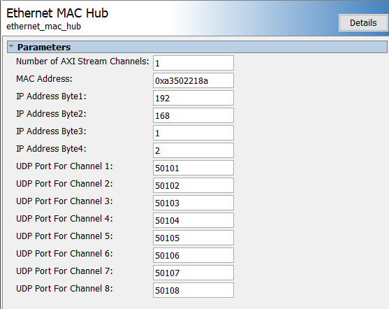
Configure these parameters:
Number of AXI Stream Channels — This parameter decides the number of AXI-stream channels in the Ethernet MAC Hub IP. Select this value as an integer from 1 to 8. The default value is
1.IP Address Byte1, IP Address Byte2, IP Address Byte3, IP Address Byte4 — These parameters set the four bytes in the range from 0 to 255 composing the UDP internet protocol (IP) address of the device. This address must match the
DeviceAddressproperty value of theaximanagerobject.UDP Port For Channel 1, UDP Port For Channel 2, UDP Port For Channel 3, UDP Port For Channel 4, UDP Port For Channel 5, UDP Port For Channel 6, UDP Port For Channel 7, UDP Port For Channel 8 — These parameters set the UDP port numbers. Specify each parameter value as an integer from 255 to 65,535. These port numbers must match the
Portproperty value of theaximanagerobject.
UDP AXI Manager IP
The UDP AXI Manager HDL IP connects the Ethernet MAC Hub IP to your application IP. The UDP AXI Manager IP acts as a bridge that translates data between an AXI peripheral and MATLAB.
Interface of UDP AXI Manager IP
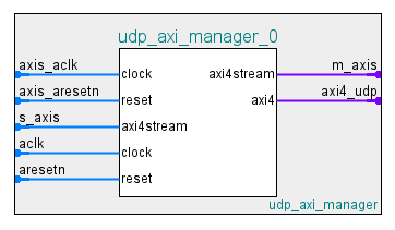
The interface of the UDP AXI Manager IP includes the ports in this table.
| Port | Description |
|---|---|
| s_axis | AXI-stream subordinate interface. |
| m_axis | AXI-stream manager interface. |
| axi4_udp | AXI4-full manager interface. |
UDP AXI Manager IP Ports
| Port | Direction | Description |
|---|---|---|
| axis_aclk | Input | Clock signal for AXI-stream interface. |
| axis_aresetn | Input | Active-low reset signal for AXI-stream interface. |
| aclk | Input | Clock signal for AXI4-full interface. |
| aresetn | Input | Active-low reset. Reset signal for AXI4-full interface. |
UDP AXI Manager IP Parameters
After instantiating the UDP AXI Manager IP in your design, open the block parameters for configuration.

Configure these parameters:
ID Width — This parameter is the ID width in bits. Its value must match the ID width of the AXI4 subordinate.
AXI Data Width — This parameter is the data bus width in bits. The IP supports 32 bits or 64 bits.
AXI Address Width — This parameter is the address bus width in bits. The IP supports 32 bits or 64 bits.
When the program is running on your FPGA board, you can create an AXI manager
object using the aximanager object. To access the
subordinate memory locations on the board, use the readmemory and writememory object functions.
Access Multiple FPGAs Connected to Single Host
When you use a programmable logic (PL) Ethernet connection, you can connect multiple FPGA boards to a single host computer to read from and write to all the boards. Consider these points when you access multiple FPGA boards:
You must connect each FPGA board by using a separate Ethernet cable.
Each connection must have its own unique IP address and port number.
You can create an
aximanagerobject for each individual board connection simultaneously.It is not necessary to release the
aximanagerobject when switching between FPGA boards.Make sure that you execute the
releasefunction for all createdaximanagerobjects at the end of execution. Releasing anyaximanagerobject prematurely leads to an error.You can access a maximum of eight FPGA boards from a single host computer.
This example shows how to write to and read from two FPGA boards connected to a
host computer. Configure the IP address for the first FPGA board to
192.168.0.2 and the port number to
50102.
axim_FPGA1 = aximanager('Intel','interface','PLEthernet', ...
'DeviceAddress','192.168.0.2','Port','50102');
Configure the IP address for the second FPGA board to
192.168.1.2 and the port number to
50101.
axim_FPGA2 = aximanager('Intel','interface','PLEthernet', ...
'DeviceAddress','192.168.1.2','Port','50101');
Write to and read from the first FPGA board.
DDRaddress = '0000000C00000000';
Data2Write_1 = (uint32(0):uint32(10));
writememory(axim_FPGA1,DDRaddress,Data2Write_1,'BurstType','Increment');
rdDDR = readmemory(axim_FPGA1,DDRaddress,10,'BurstType','Increment');
Write to and read from the second FPGA board.
BRAMaddress = '00000000';
Data2Write_2 = (uint32(11):uint32(20));
writememory(axim_FPGA2,BRAMaddress,Data2Write_2, ...
'BurstType','Increment');
rdBRAM = readmemory(axim_FPGA2,BRAMaddress,10,'BurstType','Increment');
When you no longer need to access the boards, release the Ethernet connection for
all aximanager objects.
release(axim_FPGA1);
release(axim_FPGA2);