LTE Throughput Analyzer
Generate throughput curves for physical downlink shared channel (PDSCH) conformance test analysis
Description
The LTE Throughput Analyzer app performs PDSCH demodulation performance testing. TS 36.101 [1], Annex A.3 specifies RMCs for UE performance testing.
The app also performs analysis and testing for custom user-defined measurement
channels settings. For an example, see LTE Throughput Analyzer User-Defined Testing. This approach can also be
used for simulating transmission modes 7–10, specifically, when the transmission scheme
(TxScheme) is 'Port5',
'Port7-8', 'Port8', or
'Port7-14'where DM-RS based channel estimation is required for
PDSCH demodulation. In this case, the precoding matrix W is randomly
defined per subframe according to TS 36.101 [1],
Table 8.3.1-1 for FDD and Table 8.3.2-1 for TDD.
Dialog Box Inputs and Outputs
In the LTE PDSCH Conformance Testing user interface, you can set these parameters:
| Parameter (Equivalent Field) | Values | Description | ||||||||||||||||||||
|---|---|---|---|---|---|---|---|---|---|---|---|---|---|---|---|---|---|---|---|---|---|---|
Reference channel (RC) |
| Reference measurement channel (RMC) number or type, as specified in TS 36.101, Annex A.3.
To define your own reference channel, select
The tool expects this variable to be
present in the MATLAB base workspace. Create the basic configuration structure with
the function | ||||||||||||||||||||
Duplex mode (DuplexMode) |
| Duplexing mode, specified as either:
| ||||||||||||||||||||
Transmission scheme (TxScheme) |
| PDSCH transmission scheme, specified as one of the following options.
| ||||||||||||||||||||
PDSCH Rho (dB) (Rho) | 0 (default), numeric scalar | PDSCH resource element power allocation, in dB | ||||||||||||||||||||
Propagation Model (DelayProfile) |
| Delay profile model. For more information, see Propagation Channel Models. | ||||||||||||||||||||
Doppler (Hz) (DopplerFreq) |
| Maximum Doppler frequency, in Hz. | ||||||||||||||||||||
Antenna Correlation (MIMOCorrelation) |
| Correlation between UE and eNodeB antennas | ||||||||||||||||||||
No of receive antennas (NRxAnts) | Nonnegative scalar integer | Number of receive antennas | ||||||||||||||||||||
| SNR (dB) | Numeric vector | SNR values, in dB | ||||||||||||||||||||
| Simulation length (frames) | Positive scalar integer | Simulation length, in frames | ||||||||||||||||||||
Number of HARQ processes (NHARQProcesses) | 1, 2, 3, 4, 5, 6, 7, or 8 | Number of HARQ processes per component carrier | ||||||||||||||||||||
| Perfect channel estimator |
| Channel estimator provides a perfect channel estimate
when setting is | ||||||||||||||||||||
PMI mode (PMIMode) |
| PMI reporting mode. | ||||||||||||||||||||
| Simulation results | Variable name beginning with an alphabetical character and containing alphanumeric characters. | Simulation results output variable name. When you click Generate waveform, a new variable with this name is created in the MATLAB workspace. |
Open the LTE Throughput Analyzer App
MATLAB Toolstrip: On the Apps tab, under Wireless Communications, select the LTE Throughput Analyzer app icon.
MATLAB command prompt: Enter
lteThroughputAnalyzer.
Examples
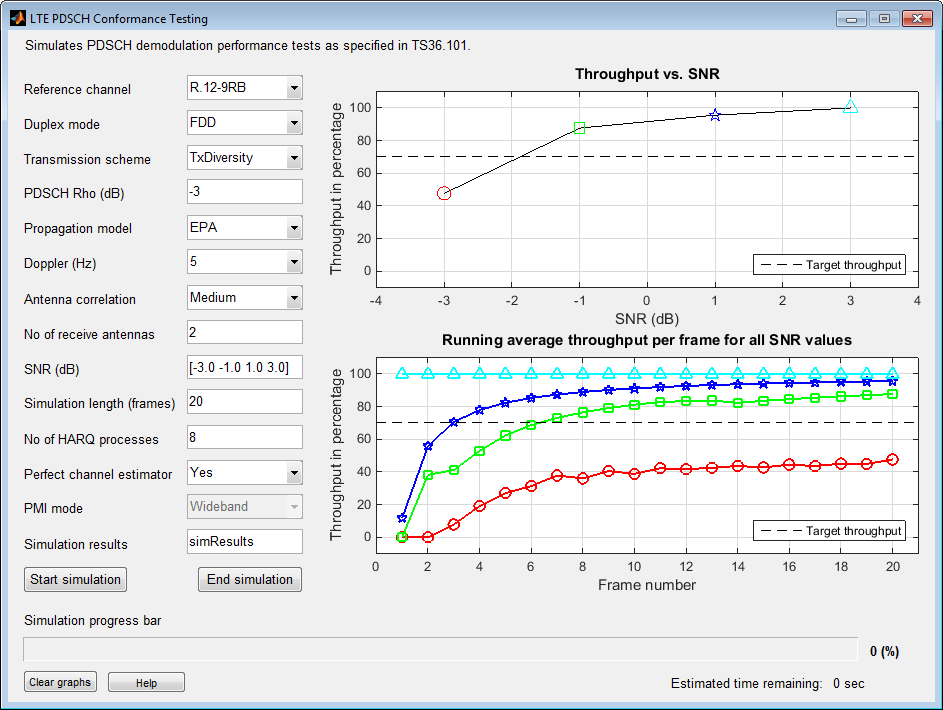
Use the LTE Throughput Analyzer app to run a conformance test for a single codeword RMC R.12-9RB for the transmit diversity transmission scheme with EPA-5 fading.
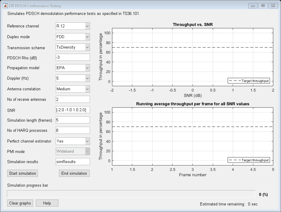
Open the LTE Throughput Analyzer app.
Adjust default runtime parameter settings:
Set Reference channel to
R.12-9RB.For SNR (dB), enter
[-3.0 -1.0 1.0 3.0].For Simulation length (frames), enter
20.
Select Start simulation. The app provides the Estimated time remaining. When the simulation finishes, the dialog box shows performance curves.
The simulation result for a 20-frame run is displayed in the MATLAB Command Window.
Result for -3 dB SNR
Throughput: 47.65%

Result for -1 dB SNR
Throughput: 87.65%

Result for 1 dB SNR
Throughput: 95.59%

Result for 3 dB SNR
Throughput: 100.00%
In addition, the simResults variable
now appears in the MATLAB workspace. View its contents.
simResults
simResults =

1x4 struct array with fields:

    throughput
    tpPerFrame
rawBEROpen the LTE throughput analyzer app and run a user-defined measurement channel. Define a custom measurement channel. You can select any RMC and change any settings, though care must be taken not to define an invalid configuration.
For this example, start with an R.3 RMC, and adjust the number of resource blocks from 50 to 30.
cmc = lteRMCDL('R.3');
cmc.NDLRB = 30
cmc = struct with fields:
RC: 'R.3'
NDLRB: 30
CellRefP: 1
NCellID: 0
CyclicPrefix: 'Normal'
CFI: 2
PCFICHPower: 0
Ng: 'Sixth'
PHICHDuration: 'Normal'
HISet: [112×3 double]
PHICHPower: 0
NFrame: 0
NSubframe: 0
TotSubframes: 10
Windowing: 0
DuplexMode: 'FDD'
PDSCH: [1×1 struct]
OCNGPDCCHEnable: 'Off'
OCNGPDCCHPower: 0
OCNGPDSCHEnable: 'Off'
OCNGPDSCHPower: 0
OCNGPDSCH: [1×1 struct]
Nfft: []
Open the LTE throughput analyzer app.
lteThroughputAnalyzer
Choose the Reference channel dropdown menu and select User defined.
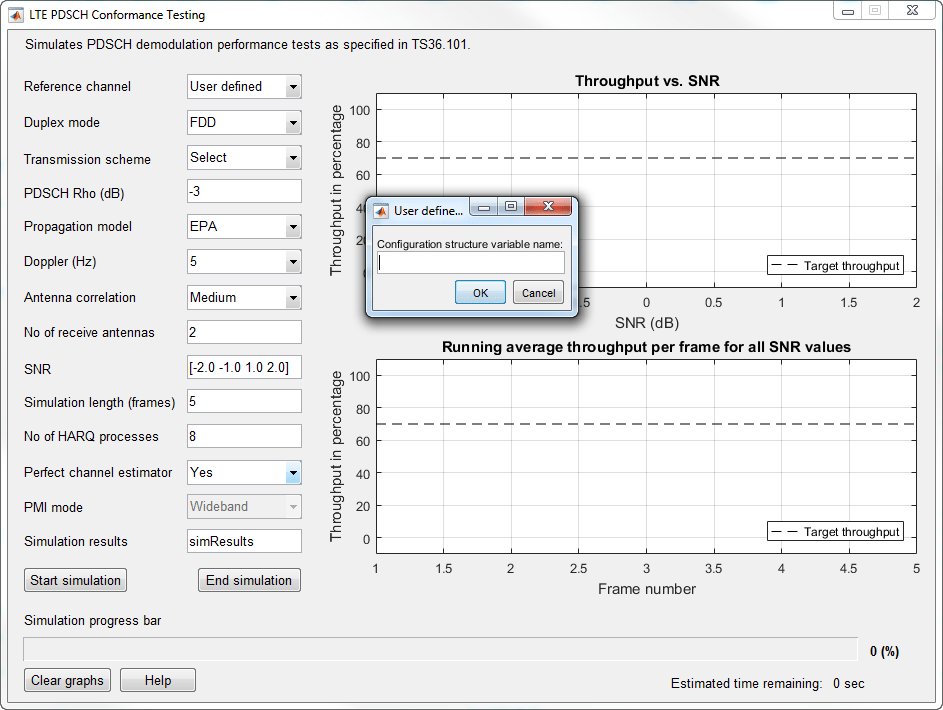
At the prompt, enter the custom measurement channel configuration structure name, cmc.
To run this user-defined configuration, click Start simulation.
Related Examples
References
[1] 3GPP TS 36.101. “Evolved Universal Terrestrial Radio Access (E-UTRA); User Equipment (UE) Radio Transmission and Reception.” 3rd Generation Partnership Project; Technical Specification Group Radio Access Network. URL: https://www.3gpp.org.
Version History
Introduced in R2014a