Overcome CAN Message Buffer Size Limitation
This example shows you the limitation of Arduino based CAN Nodes by using the automatic periodic transmit feature of Vehicle Network Toolbox™. It also shows you how to overcome the limitation by using the timer feature which is available with MATLAB®.
Required Hardware
To run this example, you will need the following hardware:
Vector CAN Case XL
Arduino Mega2560 board
Seeed Studio CAN-Bus Shield V2
Hardware Setup
Seeed Studio CAN-Bus Shield V2 mounted on Arduino Mega2560 and the Vector CAN Case XL are the CAN nodes. Use the Vector CANcable 1 and Vector CANcable A combination to connect the CANH and CANL of Vector and Arduino nodes together.
The example uses Vector CAN Case XL as the transmitter and the Arduino Mega2560 with Seeed Studio CAN-Bus Shield V2 as the receiver.
Create CAN Channels and CAN Messages
Create the transmit CAN channel object on which you can use the automatic message transmit commands using the canChannel function from Vehicle Network Toolbox.
txCh = canChannel('Vector', 'CANCaseXL 1',1);Create the receive CAN channel object.
  arduinoObj = arduino('COM11', 'Mega2560', 'Libraries', 'CAN');
  rxCh = canChannel(arduinoObj, 'Seeed Studio CAN-Bus Shield V2');
In this example, you will use a CAN database file to define and decode messages. Open the database and attach it to the CAN channels.
  db = canDatabase('demoVNT_CANdb.dbc');
  txCh.Database = db;
  rxCh.Database = db;
Create the CAN Messages
Create CAN messages for periodic transmit using the database information.
  msgFast = canMessage(db, 'EngineMsg');
  msgSlow = canMessage(db, 'TransmissionMsg');
Configure Messages for Periodic Transmit
To configure a message for periodic transmit, use the transmitPeriodic command from Vehicle Network Toolbox to specify the channel, the message to register on the channel, a mode value, and the periodic rate.
  transmitPeriodic(txCh, msgFast, 'On', 0.200);
  transmitPeriodic(txCh, msgSlow, 'On', 0.500);
Start Periodic Message Transmit
Start the channel using the start function from the Vehicle Network Toolbox before you transmit the messages. When you start a channel which has periodic messages registered, transmit begins immediately. Allow the channels to run for a short time.
  start(txCh);
  pause(2);
Modify Transmitted Data
Update the live message or signal data sent onto the CAN bus.
  msgFast.Signals.VehicleSpeed = 60;
  pause(1);
  msgFast.Signals.VehicleSpeed = 65;
  pause(1);
  msgFast.Signals.VehicleSpeed = 70;
  pause(1);
Read the Messages
Read all periodically transmitted messages.
read(rxCh, 100)
Analyze the Received Messages and take action
Having allowed the periodic messages to run for more than 5 seconds, at least 30 messages would have been transmitted. The MATLAB Support Package for Arduino Hardware provides only 10 buffers for CAN Frames. Since the messages have been received repeatedly, we see that more than 10 messages have been received. Also, only the oldest messages would be retained due to which Arduino does not receive an update to Vehicle Speed. To use Arduino as an effective receiver, in a CAN Network, we must do trial and error experiments to set it up according to the application.
To effectively receive all the messages that have been transmitted, the reading and data collection must happen in parallel to the vehicle speed update exercise. We use a timer to set up reception in Arduino.
  msgRx = [];
  stopArduinoReceptionTimer = false;
  t = timer;
  t.Name = 'ArduinoTimer';
  t.ExecutionMode = 'fixedRate';
  t.Period = 0.1;
  t.TimerFcn = @collectData;
  start(t);
  pause(2);
Modify Transmitted Data Again
Update the signal data transmitted onto the CAN bus.
  msgFast.Signals.VehicleSpeed = 60;
  pause(1);
  msgFast.Signals.VehicleSpeed = 45;
  pause(1);
  msgFast.Signals.VehicleSpeed = 10;
  pause(1);
Analyze the Periodic Transmit Behavior
Stop the transmission channel and the timer we created for Arduino to receive messages. You can analyze the distribution of messages by plotting the identifiers of each message against their timestamps. Notice the difference between how often the two messages appear according to their periodic rates.
  stop(txCh);
  stopArduinoReceptionTimer = true;
  pause(1);
  plot(msgRx.Time, msgRx.ID, 'x')
  ylim([0 400])
  title('Message Distribution', 'FontWeight', 'bold')
  xlabel('Timestamp')
  ylabel('CAN Identifier')

For further analysis, separate the two messages into individual timetables.
  msgRxFast = msgRx(strcmpi('EngineMsg', msgRx.Name), :);
  msgRxFast(1:10, :)
  msgRxSlow = msgRx(strcmpi('TransmissionMsg', msgRx.Name), :);
  msgRxSlow(1:10, :)
Analyze the timestamps of each set of messages to see how closely the average of the differences corresponds to the configured periodic rates.
  avgPeriodFast = mean(milliseconds(diff(msgRxFast.Time)))
  avgPeriodSlow = mean(milliseconds(diff(msgRxSlow.Time)))
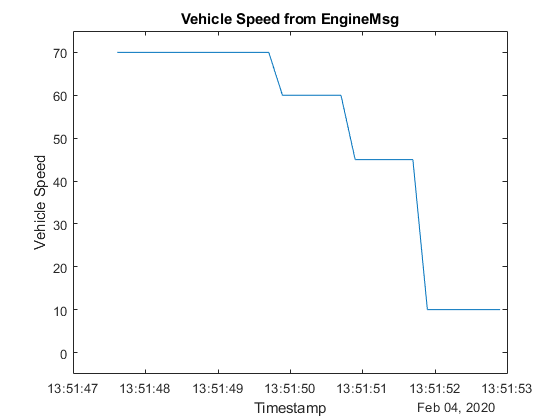
A plot of the received signal data reflects the updates in the message data sent on the CAN bus.
  signalTimetable = canSignalTimetable(msgRx, 'EngineMsg');
  signalTimetable(10:25, :)
  plot(signalTimetable.Time, signalTimetable.VehicleSpeed)
  title('Vehicle Speed from EngineMsg', 'FontWeight', 'bold')
  xlabel('Timestamp')
  ylabel('Vehicle Speed')
  ylim([-5 75])

View Messages Configured for Periodic Transmit
To see messages configured on a channel for periodic transmit, use the transmitConfiguration function from the Vehicle Network Toolbox.
transmitConfiguration(txCh)
Clean Up
When finished, clear the connections to the hardware and the created messages.
  clear txCh
  clear arduinoObj
  clear rxCh
  clear msgFast
  clear msgSlow
  clear msgRx
  clear msgRxFast
  clear msgRxSlow
  clear signalTimetable
Routine to collect data using Arduino
The collectData function is used to read CAN Messages in parallel to data update. For more information on the collectData function, execute the following command in the MATLAB command line:
open('collectData.m')