Use BeagleBone Black ADC to Capture Analog Data
This example shows how to use the BeagleBone® Black ADC to perform a simple voltage measurement using a potentiometer.
The BeagleBone Black hardware has six analog-to-digital converter (ADC) modules
associated with six analog input pins. You can use these pins to measure positive
voltages in the range 0 V (GND_ADC) -
1.8 V (VDD_ADC).
In addition to your BeagleBone Black board and USB cable, you must have the following equipment:
1 10 kΩ potentiometer
Breadboard and jumper cables
The potentiometer (POT) is a three-terminal device with terminals
1 and 3 comprising the end points of a resistor embedded in the POT.
The second terminal is connected to a variable wiper. As the wiper
moves, the resistance values across terminals 1 and 2 and terminals
2 and 3 change. In this circuit, POT acts as a variable voltage divider.
As you move the knob of the potentiometer, the voltage seen at terminal
2 changes between 1.8 V (VDD_ADC)
and 0 V (GND_ADC).
Caution
Never connect a voltage greater than
1.8 Vacross the ADC pins. Voltages greater than1.8 Vcan damage the board.Always connect the negative (ground) side of a voltage source to
GND_ADC. The ADC measures positive voltages only. A reversed connection can damage the board.
Configure the BeagleBone Black hardware.
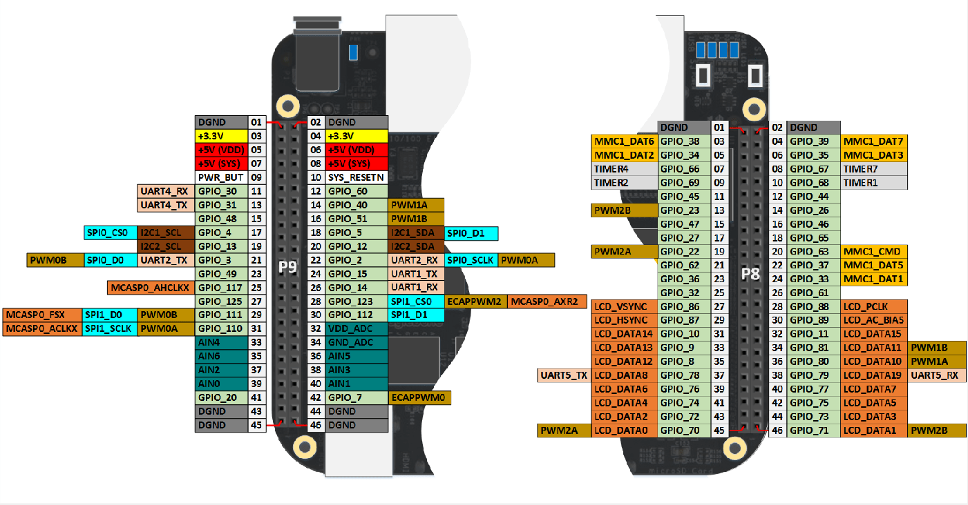
Insert a black probe lead into the
GND_ADCsocket (P8_34).Insert a white probe lead into the
VDD_ADCsocket (P8_32).Insert a red probe lead into the
AIN0socket (P8_39)Connect the white lead to terminal 1 of the POT. Connect the black lead to terminal 3 of the POT. Connect the red lead to terminal 2 of the POT.
Start MATLAB®.
Connect the BeagleBone Black board to a host computer USB port and wait about 30 seconds for the board to start.
Connect the BeagleBone Black driver interface to the board.
bbb = beaglebone
bbb =

  beaglebone with properties:

           DeviceAddress: '192.168.7.2'
               BoardName: 'BeagleBone Black Rev 00C0'
           AvailableLEDs: {'USR0'  'USR1'  'USR2'  'USR3'}
    AvailableDigitalPins: {1x29 cell}
     AvailableAnalogPins: {'AIN0'  'AIN1'  'AIN2'  'AIN3'  'AIN4'  'AIN5'  'AIN6'}
        AvailablePWMPins: {}
    AvailableSPIChannels: {}
       AvailableI2CBuses: {'i2c-1'}
    AvailableSerialPorts: {}
        AvailableWebcams: {}
Verify that
'AIN0'is an available analog pin.bbb.AvailableAnalogPins
ans =

    'AIN0'    'AIN1'    'AIN2'    'AIN3'    'AIN4'    'AIN5'    'AIN6'
Set the POT to its lowest position. Read the voltage.
v_AA = readVoltage(bbb, 'AIN0')vv_AA = 1.8Set the POT to its highest position. Read the voltage.
v_AA = readVoltage(bbb, 'AIN0')vv_AA = 0.0