Field-Oriented Control of Six-Phase PMSM
This example shows how to control the torque of an asymmetric six-phase permanent magnet synchronous motor (PMSM) using field-oriented control (FOC).
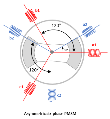
You can consider the six windings of a six-phase PMSM as two sets of three-phase windings:
a1, b1, c1
a2, b2, c2
Six-phase PMSMs can have different configurations based on the spatial angle (or spatial shift) between the two sets of three-phase windings. An asymmetric six-phase PMSM has a spatial angle of 30 electrical degrees as shown in the following figure.

Plant Model
The example uses the block PMSM (Six-Phase) (Simscape Electrical) to implement a plant model for an asymmetric six-phase PMSM. The plant model uses two separate inverters to drive the motor. These inverters use separate PWM switching sequences to generate two sets of three-phase voltages that drive the corresponding three-phase motor windings.
Controller Algorithm
The example provides the following two control algorithms to control the six-phase motor:
Double d-q control - This control algorithm uses a control strategy that considers the six-phase PMSM as a combination of two three-phase motors. It uses a separate current control algorithm (that utilizes Clarke, Park, and Inverse Park mathematical transforms) to control the torque associated with each three-phase motor.
If you select this control algorithm, the example uses the variant subsystem SixPhasePMSMTorqueControl/Torque Control/Controller/Double d-q Control to control the three-phase winding sets.
VSD-based control - This control algorithm uses a control strategy that considers the six-phase PMSM as a single unit. The variant uses a single current control algorithm (that utilizes VSD and inverse VSD transforms) to directly control the torque of the six-phase PMSM.
If you select this control algorithm, the example uses the variant subsystem SixPhasePMSMTorqueControl/Torque Control/Controller/VSD based Control to control the six-phase PMSM.
Note: The example uses the FOC Default Controller Gains block available in the SixPhasePMSMTorqueControl/Torque Control/Control gain computation/Gain Computation - DQ subsystem to compute the gains ( and
and  ) for the PI controllers implemented by the two control algorithms.
Model
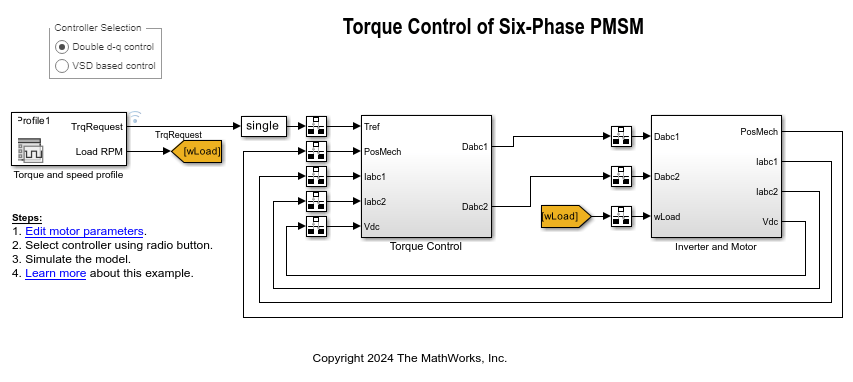
The example includes the Simulink® model SixPhasePMSMTorqueControl.
You can use this model for simulation.

Required MathWorks Products
Motor Control Blockset™
Simscape™ Electrical™
Prerequisites
1. Obtain the motor parameters. The Simulink model uses default motor parameters that you can replace with the values from either the motor datasheet or other sources.
2. Update the motor and inverter parameters in the model initialization script SixPhasePMSMTorqueControlData associated with the Simulink model. For more details about the model initialization script, see Model Initialization Script.
Simulate Model
This example supports simulation. Follow these steps to simulate the Simulink model.
1. Open the Simulink model SixPhasePMSMTorqueControl included with this example.
2. Use the following radio buttons available in the Controller Selection section to select a control algorithm that you want to use for the asymmetric six-phase PMSM:
Double d-q control
VSD based control
3. To simulate the Simulink model, click Run on the Simulation tab.
4. To view and analyze the simulation results, click Data Inspector on the Simulation tab.
See Also
6-Phase VSD Transform | 6-Phase Inverse VSD Transform | PMSM (Six-Phase) (Simscape Electrical) | Park Transform | Inverse Park Transform | Field-Oriented Current Controller | FOC Default Controller Gains | Clarke Transform | PWM Reference Generator
Topics
- Six-Phase PMSM Torque Control (Simscape Electrical)
- Six-Phase PMSM Velocity Control (Simscape Electrical)