FOC Default Controller Gains
Compute empirical PI controller gains for the field-oriented control (FOC) based algorithms at run time
Since R2023b
Libraries:
Motor Control Blockset /
Controls /
Controllers
Description
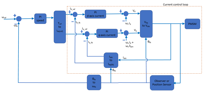
The FOC Default Controller Gains block computes empirical controller
gains for PI controllers used in the field-oriented control (FOC) based algorithms. It
computes the PI controller gains used in the current controller, speed controller, and
field-weakening controller using the d-q frame of reference-based motor
model. The block uses the function mcb_SetControllerParameters
internally to compute the control gains. For more details about this function, see Obtain Controller Gains.
The block accepts motor parameters along with the current and speed controller sample times to generate a bus containing proportional and integral control gains, which you can use for PI controllers in an FOC-based algorithm.
The block uses the value that you specify at the SlowdownFactor input port to modify the PI gains output to make them less aggressive and slow down the system response.
Note
The block uses empirical calculation to compute the control gains. The gains computed by the block might not be optimal and might require additional tuning to improve dynamic performance.
It is recommended that you use the block inside a triggered subsystem or a slow-running control loop.
The block inputs accept values greater than zero.
Examples
Swap Motors with Single Model Deployment of Sensor-Based FOC Algorithm
Run a permanent magnet synchronous motor (PMSM) in an industrial drive application setup using position-sensor-based field-oriented control (FOC). Industrial drives enable you to swap motors in real-time without repeated deployment of code. An industrial drive setup needs a fixed inverter and software that has the ability to adapt the control algorithm according to the new motor using only the updated nameplate parameters.
Swap Motors with Single Deployment of Sensorless FOC Algorithm
Run a permanent magnet synchronous motor (PMSM) in an industrial drive application setup using a sensorless field-oriented control (FOC) algorithm. The example uses a sensorless Flux Observer to estimate the motor position. Industrial drives enable you to replace a motor with a new one without repeated deployment of code. An industrial drive setup needs only nameplate parameters to adapt the software to the new motor.
Generate Motor Control Models for Selected Algorithm and Hardware
Use Motor Control Blockset™ to generate a Simulink® model that is configured for a specific hardware and motor control technique.
Ports
Input
Rs
— Stator resistance
scalar
Stator resistance of the motor (in ohms).
Dependencies
To enable this port, select one or both of these parameters in the Block Output section of the Parameters tab:
Current controller (d,q-axes)
Field-weakening controller
Data Types: single
| double
Ld — d-axis inductance
scalar
The d-axis inductance of a permanent magnet synchronous motor (PMSM) (in henries).
Dependencies
To enable this port:
Set the Motor selection parameter to
PMSM
.Select the Current controller (d,q-axes) parameter available in the Block Output section of the Parameters tab.
Data Types: single
| double
Lq — q-axis inductance
scalar
The q-axis inductance of a permanent magnet synchronous motor (PMSM) (in henries).
Dependencies
To enable this port:
Set the Motor selection parameter to
PMSM
.Select one or both of the these parameters in the Block Output section of the Parameters tab:
Current controller (d,q-axes)
Field-weakening controller
Data Types: single
| double
Lm — Magnetizing inductance
scalar
The magnetizing inductance of an AC induction motor (ACIM) (in henries).
Dependencies
To enable this port:
Set the Motor selection parameter to
ACIM
.Select one or both of the these parameters in the Block Output section of the Parameters tab:
Current controller (d,q-axes)
Field-weakening controller
Data Types: single
| double
Lls — Stator leakage inductance
scalar
The stator leakage inductance of an AC induction motor (ACIM) (in henries).
Dependencies
To enable this port:
Set the Motor selection parameter to
ACIM
.Select one or both of the these parameters in the Block Output section of the Parameters tab:
Current controller (d,q-axes)
Field-weakening controller
Data Types: single
| double
Llr — Rotor leakage inductance
scalar
The rotor leakage inductance of an AC induction motor (ACIM) (in henries).
Dependencies
To enable this port:
Set the Motor selection parameter to
ACIM
.Select one or both of the these parameters in the Block Output section of the Parameters tab:
Current controller (d,q-axes)
Field-weakening controller
Data Types: single
| double
J — Motor inertia
scalar
Inertia of the motor (in kg.m2).
Dependencies
To enable this port, select the Speed controller parameter in the Block Output section of the Parameters tab.
Data Types: single
| double
Ts — Current controller sample time
scalar
Sample time (in seconds) of the current PI controller used in the FOC based motor control algorithm.
Data Types: single
| double
Tsc — Speed controller sample time
scalar
Sample time (in seconds) of the speed PI controller used in the FOC based motor control algorithm.
Dependencies
To enable this port, select the Speed controller parameter in the Block Output section of the Parameters tab.
Data Types: single
| double
SlowdownFactor — Factor to slow down system response
scalar in the range of [1, 20]
A factor, in the range of [1, 20], that you can provide to modify the output PI gains. A higher value makes the controller parameters less aggressive and slows down the system response.
Dependencies
To enable this port, clear the Specify filter and sensor delays parameter available in the Delays tab.
Data Types: single
| double
IsenseMax — Maximum measurable peak-neutral current
scalar
Maximum AC current magnitude (peak value) in an inverter-based motor drive system (in amperes).
Dependencies
To enable this port, either:
Select the Speed controller parameter in Block output section of Parameters tab.
or
Select the Current controller (d,q-axes) parameter in Block output section of Parameters tab.
Set the Output unit parameter to
Per-Unit
.
Data Types: single
| double
Vdc — DC link voltage
scalar
DC link voltage of the inverter (in volts). The block uses as a base value for per-unit calculations when you set the
Output unit parameter to
Per-Unit
.
Dependencies
To enable this port:
Select the Current controller (d,q-axes) parameter in Block output section of Parameters tab.
Set the Output unit parameter to
Per-Unit
.
Data Types: single
| double
Nbase — Motor rated speed
scalar
Base value of the speed of the motor (in rpm) for per-unit computation.
Select the Speed controller parameter in Block output section of Parameters tab.
Set the Output unit parameter to
Per-Unit
.
Data Types: single
| double
Output
PI Gains — PI controller gains
bus
Control gains of one or more of these PI controllers used in an FOC motor control algorithm based on the Block output parameter selection:
d- and q-axis current controller
Speed controller
Field-weakening controller
The following table summarizes the components of the PI Gains output bus:
Type of PI Controller | Bus component | Description | ||
---|---|---|---|---|
d-axis current PI controller | Daxis_Kp | Control gain Kp of the d-axis current PI controller | ||
Daxis_Ki | Control gain Ki of the d-axis current PI controller | |||
Daxis_Ki*Ts | Control gain Ki of the d-axis current PI controller multiplied with the current controller sample time (TS) | |||
q-axis current PI controller | Qaxis_Kp | Control gain Kp of the q-axis current PI controller | ||
Qaxis_Ki | Control gain Ki of the q-axis current PI controller | |||
Qaxis_Ki*Ts | Control gain Ki of the q-axis current PI controller multiplied with the current controller sample time (TS) | |||
Speed PI controller | Speed_Kp | Control gain Kp of the speed PI controller | ||
Speed_Ki | Control gain Ki of the speed PI controller | |||
Speed_Ki*Tsc | Control gain Ki of the speed PI controller multiplied with the speed controller sample time (TSC) | |||
Field-weakening PI controller | FWC_Kp | Control gain Kp of the field-weakening PI controller | ||
FWC_Ki | Control gain Ki of the field-weakening PI controller | |||
FWC_Ki*Ts | Control gain Ki of the field-weakening PI controller multiplied with the current controller sample time (TS) |
Data Types: single
| double
Status — PI gains computation status
true | false
Computation status of the PI gains, returned as one of these values:
True indicates that the block has successfully computed the PI controller gains available at the PI Gains output port.
False indicates that the block could not compute the PI controller gains as the value of one or more inputs was incorrect.
Data Types: Boolean
Parameters
Motor selection — Type of motor
PMSM
(default) | ACIM
The type of motor for which you are implementing the control algorithm:
ACIM — AC induction motor
PMSM — Permanent magnet synchronous motor
Output unit — Unit of the block output
SI Unit
(default) | Per-Unit
Unit of the elements in the bus that the block outputs at the PI Gains output port.
Block Output — Output of the block
Current controller (d,q-axes)
| Field-weakening controller
| Speed controller
Enable the block to compute and output one or more of the following elements through the PI Gains port:
Current controller (d,q-axes)
— Control gains (Kp and Ki) of the PI controllers for d- and q-axis current control.Field-weakening controller
— Control gains (Kp and Ki) of the PI controller operating in the field-weakening region.Speed controller
— Control gains (Kp and Ki) of the speed PI controller.
Delays
Specify filter and sensor delays — Enable addition of filter and sensor delays
off
(default) | on
Select this option to specify speed filter delay and current and speed sensor delays. When you select this parameter, the block enables the Current sensor delay (s), Speed sensor delay (s), and Speed filter delay (s) parameters.
Current sensor delay (s) — Delay due to current sensor
50e-6
(default) | scalar
Time delay (in seconds) due to the current sensor.
Dependencies
To enable this parameter, select the Specify filter and sensor delays parameter.
Speed sensor delay (s) — Delay due to speed sensor
50e-6
(default) | scalar
Time delay (in seconds) due to the speed sensor.
Dependencies
To enable this parameter, select the Specify filter and sensor delays parameter.
Speed filter delay (s) — Delay due to speed filtering
0.02
(default) | scalar
Time delay (in seconds) introduced by speed filtering.
Dependencies
To enable this parameter, select the Specify filter and sensor delays parameter.
Extended Capabilities
C/C++ Code Generation
Generate C and C++ code using Simulink® Coder™.
Version History
Introduced in R2023b
MATLAB Command
You clicked a link that corresponds to this MATLAB command:
Run the command by entering it in the MATLAB Command Window. Web browsers do not support MATLAB commands.
Select a Web Site
Choose a web site to get translated content where available and see local events and offers. Based on your location, we recommend that you select: United States.
You can also select a web site from the following list
How to Get Best Site Performance
Select the China site (in Chinese or English) for best site performance. Other MathWorks country sites are not optimized for visits from your location.
Americas
- América Latina (Español)
- Canada (English)
- United States (English)
Europe
- Belgium (English)
- Denmark (English)
- Deutschland (Deutsch)
- España (Español)
- Finland (English)
- France (Français)
- Ireland (English)
- Italia (Italiano)
- Luxembourg (English)
- Netherlands (English)
- Norway (English)
- Österreich (Deutsch)
- Portugal (English)
- Sweden (English)
- Switzerland
- United Kingdom (English)
Asia Pacific
- Australia (English)
- India (English)
- New Zealand (English)
- 中国
- 日本Japanese (日本語)
- 한국Korean (한국어)