Isotropic Antenna Element
Support for Isotropic Antenna Elements
An isotropic antenna element radiates equal power in all directions.
If the antenna element is backbaffled, the antenna radiates equal
power in all directions for which the azimuth angle satisfies –90
≤ φ ≤ 90 and zero power in all other
directions. To construct an isotropic antenna, use the phased.IsotropicAntennaElement System object™.
When you use this object, you must specify these antenna properties:
FPGA
The operating frequency range of the antenna using the
FrequencyRangeproperty.Whether or not the response of the antenna is backbaffled at azimuth angles outside the interval [–90,90] using the
BackBaffledproperty.
You can determine the voltage response of the isotropic antenna element at specified frequencies and angles by executing the System object.
Backbaffled Isotropic Antenna
This example shows how to construct a backbaffled isotropic antenna element with a uniform frequency response over a range of azimuth angles from [-180,180] degrees and elevation angles from [-90,90] degrees. The antenna operates between 300 MHz and 1 GHz. Show the antenna pattern at 1 GHz.
fc = 1e9;
antenna = phased.IsotropicAntennaElement(...
    'FrequencyRange',[300e6 1e9],'BackBaffled',false);
pattern(antenna,fc,[-180:180],[-90:90],'CoordinateSystem','polar',...
    'Type','power')

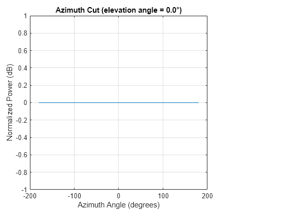
Using the antenna pattern method, plot the antenna response at zero degrees elevation for all azimuth angles at 1 GHz.
pattern(antenna,1e9,[-180:180],0,'CoordinateSystem','rectangular',...
    'Type','powerdb')

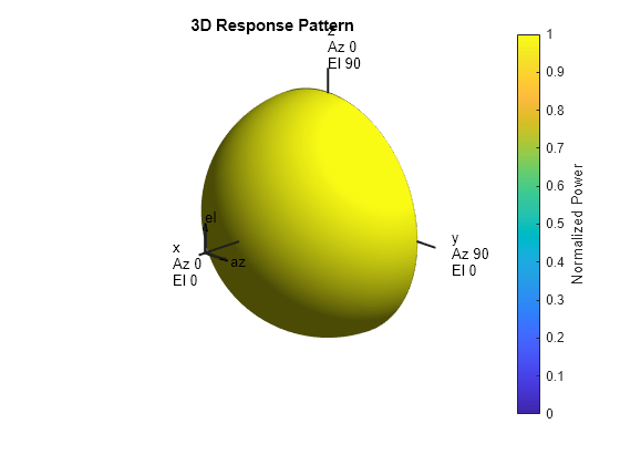
Setting the BackBaffled property to true restricts the antenna response to azimuth angles in the interval [-90,90] degrees. In this case, plot the antenna response in three dimensions.
antenna.BackBaffled = true;
pattern(antenna,fc,[-180:180],[-90:90],'CoordinateSystem','polar',...
    'Type','power')

Response of Backbaffled Isotropic Antenna Element
This example shows how to design a backbaffled isotropic antenna element and obtain its response. First, construct an X-band isotropic antenna element that operates from 8 to 12 GHz setting the Backbaffle property to true. Obtain the antenna element response at 4, 10, and 14 GHz at azimuth angles between -100 and 100 degrees in 50 degree increments. All elevation angles are by default equal to zero.
antenna = phased.IsotropicAntennaElement(...
    'FrequencyRange',[8e9 12e9],'BackBaffled',true);
respfreqs = [6:4:14]*1e9;
respazangles = -100:50:100;
anresp = antenna(respfreqs,respazangles)
anresp = 5×3

     0     0     0
     0     1     0
     0     1     0
     0     1     0
     0     0     0
The antenna response in anresp is a matrix having row dimension equal to the number of azimuth angles in respazangles and column dimension equal to the number of frequencies in respfreqs. The response voltage in the first and last columns of anresp are zero because those columns contain the antenna response at 6 and 14 GHz, respectively. These frequencies lie outside the antenna operating frequency range. Similarly, the first and last rows of anresp contain all zeros because BackBaffled property is set to true. The first and last row contain the antenna response at azimuth angles outside of [-90,90].
To obtain the antenna response at nonzero elevation angles, input the angles to the object as a 2-by-M matrix where each column is an angle in the form [azimuth;elevation].
release(antenna)
respelangles = -90:45:90;
respangles = [respazangles; respelangles];
anresp = antenna(respfreqs,respangles)
anresp = 5×3

     0     1     0
     0     1     0
     0     1     0
     0     1     0
     0     1     0
Notice that anresp(1,2) and anresp(5,2) represent the antenna voltage response at the azimuth-elevation angle pairs (-100,-90) and (100,90) degrees. Although the azimuth angles lie in the baffled region, because the elevation angles are equal to +/- 90 degrees, the responses are unity. In this case, the resulting elevation cut degenerates to a point.