Analysis of a Radial Stub Bandstop Filter
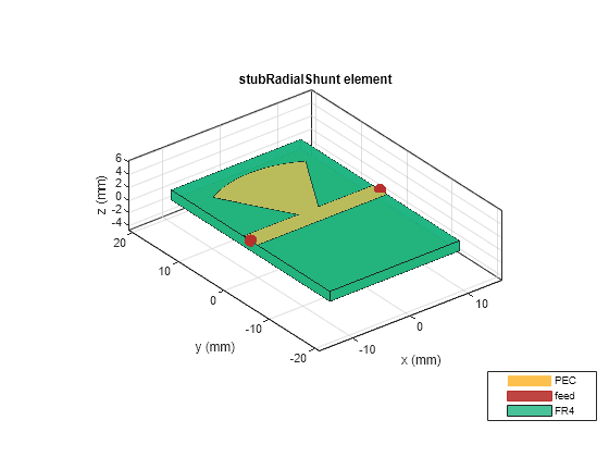
In this example, we use the RF PCB Toolbox's stubRadialShunt catalog element to construct and analyze the bandstop filter shown in Figs. 1 and 2 of the reference [1]. Excellent agreement is found with the results reported in [1].
Problem Setup
We use the frequency range 0.2 GHz to 10 GHz for analysis, following Fig. 2 of [1].
freq = 0.2e9:0.2e9:10e9;
The three parameters required to characterize the stubRadialShunt are the outer radius of the stub, the inner radius of the stub, and the angle of the stub as shown in its . The reference [1] uses the same conventions and gives all dimensions and material properties in Section II after Fig. 2.
ro        = 16e-3;    % Outer radius of stub (m)
ri        = 3.5e-3;   % Inner radius of stub (m)
thetaR    = 60;       % Angle subtended by stub (degrees)
epsr      = 4.4;      % Dielectric relative permittivity
thickness = 1.56e-3;  % Dielectric thickness (m)
lossTang  = 0.016;    % Dielectric loss tangent
From these parameters, we can fully define the device.
% Prepare substrate
sub1 = dielectric('FR4');
sub1.EpsilonR = epsr;
sub1.LossTangent = lossTang;
sub1.Thickness = thickness;

% Set up stubRadialShunt
object = stubRadialShunt;
object.OuterRadius = ro;
object.InnerRadius = ri;
object.Angle = thetaR;
object.PortLineLength = 14.9e-3 * 1.5; % The port line length must extend beyond the ends of the radial stub
object.PortLineWidth = object.InnerRadius * cosd(thetaR/2) * 1.02; % 2% increase in line width ensures connection to the stub.

object.Height = thickness;
object.Substrate = sub1;
object.GroundPlaneWidth = 35e-3; % the ground plane must fully underlie the stub
object.GroundPlaneLength = object.PortLineLength;

figure; show(object);

Solution and Comparison
At this point, we can mesh and solve the structure. The maximum and minimum edge lengths below are chosen to place at least two triangles across the trace's width, which is a conservative decision that typically produces reliable results.
figure; mesh(object, 'MaxEdgeLength', 3e-3, 'MinEdgeLength', 1.5e-3);

sp = sparameters(object, freq);
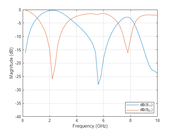
figure; rfplot(sp, [1 2], 1);
legend('Location', 'southeast')
ylim([-40 0]);

The S11 and S21 magnitude results show near 1-1 agreement with the red and blue curves shown in Fig. 2 of [1]. Note that the sharp changes in S21 around 2.2 GHz and in S11 around 5.5 GHz would be resolved with tighter frequency spacing.
References
[1] Singh PK, Tiwary AK. Novel compact dual bandstop filter using radial stub. Microw Rev. 2015 Sep 1;21(1):17-22.
