Design of Quarter-Wave Transformer for Impedance Matching Applications
This example shows how to design the Quarter-wave transformer for impedance matching applications by using the pcbComponent, microstripLine, and traceRectangular object in the RF PCB Toolbox.
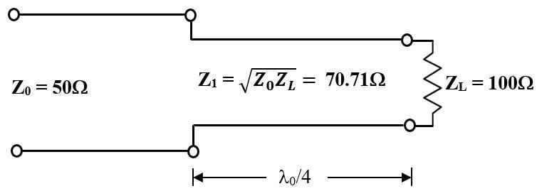
Quarter-wave transformer is a simple and useful circuit for matching the real impedance of a terminating load () to the characteristic impedance of the feeding transmission line () as depicted in the given figure. The characteristic impedance of the quarter-wave transformer is calculated as [1]. This example is to design a single section quarter-wave transformer to match the load to a transmission line at an operating frequency of . The calculated characteristic impedance of the quarter-wave transformer is .
Design of Single Section Quarter-Wave Transformer
Use the design function on the microstripLine object to create the input transmission line andquarter-wave transformer's Length and Width dimension for the operating frequency of . The default substrate for microstripLine is Teflon with thickness of .
freq = 2e9;
m50 = design(microstripLine,freq,Z0=50,LineLength=0.05); % input transmission line
m70 = design(microstripLine,freq,Z0=70.71,LineLength=0.25); % section 1
Use the traceRectangular object to create the ground plane, input transmission line, and quarter-wave transmission line shapes.
% ground plane dimension
gndL = 2*m50.Length+m70.Length;
gndW = 5*m50.Width;

ground = traceRectangular("Length",gndL,"Width",gndW);
% input transmission line
Z0 = traceRectangular("Length",m50.Length,"Width",m50.Width,...
    "Center",[-gndL/2+m50.Length/2 0]);
% First section Quarter-wave transformer
Z1 = traceRectangular("Length",m70.Length,"Width",m70.Width,"Center",...
    [-gndL/2+m50.Length+m70.Length/2 0]);

qline = Z0 + Z1;
Use the pcbComponent to create the quarter-wave transformer and use the lumpedElement for the terminating load of and place it at the end of the quarter-wave transformer and use a via to connect the load to ground.
pcb =pcbComponent;
pcb.BoardShape = ground;
pcb.BoardThickness = m50.Height;
pcb.Layers = {qline,m50.Substrate,ground};
pcb.FeedDiameter = m50.Width/2;
pcb.FeedLocations = [-gndL/2 0 1 3];
pcb.ViaLocations = [-gndL/2+m50.Length+m70.Length,0,1,3];
pcb.ViaDiameter = m70.Width/2;
% Load
ZL = lumpedElement;
ZL.Impedance = 100;
ZL.Location = [-gndL/2+m50.Length+m70.Length,0,pcb.BoardThickness];
pcb.Load = ZL;
% show the single section quarter-wave transformer
figure;show(pcb)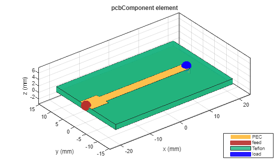
Use the sparameters function to calculate the S parameters and plot it using the rfplot function.
sparams = sparameters(pcb,linspace(100e6,8e9,51));
figure; rfplot(sparams)
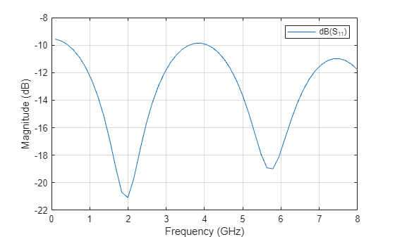
It is observed from the values that the impedance is perfectly matched at the desired frequency of where the value of magnitude is less than with the bandwidth of . Matching also occurs at frequencies where the has a length of
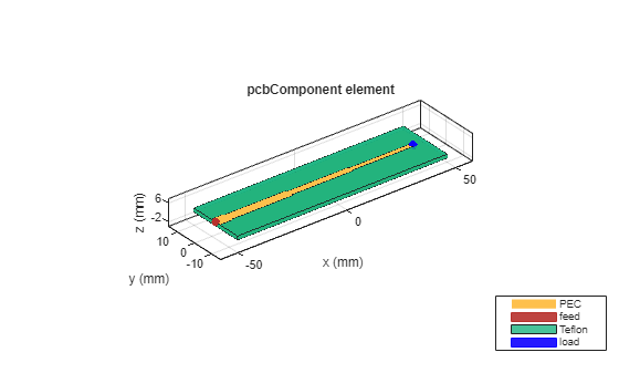
Design of Multisection Quarter-Wave Transformer
In general, the single section transformer may be sufficient for narrow band impedance match. This transformer can be extended to multisection in a methodical manner to yield optimum matching characteristics over a wider bandwidth [1]. The following example is for the design of three section Chebyshev matching transformer to match a load to a with ripple level = . Each section's characteristic impedance is computed using the formulas given in [1] and the values are and . The three section Chebyshev matching transformer is designed by using same steps described in the design of single section quarter-wave transformer.
m50 = design(microstripLine,freq,"Z0",50,"LineLength",0.05); % input transmission line
m57 = design(microstripLine,freq,"Z0",57.5,"LineLength",0.25); % section 1
m70 = design(microstripLine,freq,"Z0",70.7,"LineLength",0.25); % section 2
m87 = design(microstripLine,freq,"Z0",87,"LineLength",0.25); % section 3
% ground plane dimension
gndL = 2*m50.Length+m57.Length+m70.Length+m87.Length;
gndW = 5*m50.Width;

ground = traceRectangular("Length",gndL,"Width",gndW);
% input transmission line
Z0 = traceRectangular("Length",m50.Length,"Width",m50.Width,...
    "Center",[-gndL/2+m50.Length/2 0]);
% First section Quarter-wave transformer
Z1 = traceRectangular("Length",m57.Length,"Width",m57.Width,"Center",...
    [-gndL/2+m50.Length+m57.Length/2 0]);
% Second section Quarter-wave transformer
Z2 = traceRectangular("Length",m70.Length,"Width",m70.Width,"Center",...
    [-gndL/2+m50.Length+m57.Length+m70.Length/2 0]);
% Third section Quarter-wave transformer
Z3 = traceRectangular("Length",m87.Length,"Width",m87.Width,"Center",...
    [-gndL/2+m50.Length+m57.Length+m70.Length+m87.Length/2 0]);

qline = Z0+Z1+Z2+Z3;
% create pcbComponent
pcb =pcbComponent;
pcb.BoardShape = ground;
pcb.BoardThickness = m50.Height;
pcb.Layers ={qline,m50.Substrate,ground};
pcb.FeedDiameter = m50.Width/2;
pcb.FeedLocations = [-gndL/2 0 1 3];
pcb.ViaLocations = [-gndL/2+m50.Length+m57.Length+m70.Length+m87.Length,0,1,3];
pcb.ViaDiameter = m87.Width/2;
% Load
ZL = lumpedElement;
ZL.Impedance = 100;
ZL.Location = [-gndL/2+m50.Length+m57.Length+m70.Length+m87.Length,0,pcb.BoardThickness];
pcb.Load = ZL;
% show the three section quarter-wave transformer
figure;show(pcb)
% Analysis
sparams3 = sparameters(pcb,linspace(100e6,8e9,51));
figure; rfplot(sparams3)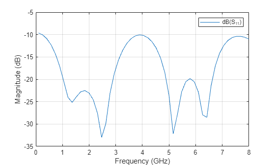
Comparison of S parameters
figure; rfplot(sparams,'-.')
hold on
rfplot(sparams3)
legend('dB(S_{11}) for N=1','dB(S_{11}) for N=3','Location','northeast')

From the comparison the s-parameters plot for single section and three section quarter-wave transformers designed at , it is observed that the bandwidth achieved for three section quarter-wave transformer is with improved impedance matching characteristics.Therefore, it is evident that wider bandwidth is achieved for quarter-wave transformers with multiple sections.
References
[1] David M. Pozar, Microwave Engineering, pp. 246-261, Edition, John Wiley & Sons, 2012.