Arbitrary Response FIR
Design finite impulse response filter of arbitrary response
Description
An arbitrary response filter preserves or attenuates the energy of an input signal following a specified frequency-dependent amplitude profile. A finite impulse response (FIR) filter computes an output signal as a running weighted average of input samples.
You can specify an arbitrary response in these ways:
Arbitrary amplitude — Specify the amplitude of the frequency response in linear units.
Arbitrary full response — Specify complete frequency response, either as magnitudes and phases or as complex values.
Signal Processing Toolbox™ provides different ways to design arbitrary response FIR filters:
designfiltfunction — Design an arbitrary response FIR filter at the command line or in a script.To specify arbitrary amplitudes, use
"arbmagfir"as the first argument when you call the function.To specify arbitrary full responses in complex-valued form, use
"arbmagnphasefir"as the first argument when you call the function. If you have magnitudes and phases, convert them to real and imaginary values or use the Filter Design Assistant. You must have a DSP System Toolbox™ license to use this functionality.
For an example, see Design Arbitrary Response FIR Filter Using designfilt.
Filter Designer app — Design an arbitrary response FIR filter interactively. Export your design to the MATLAB® workspace or to a file.
To specify arbitrary amplitudes, navigate to the Response section of the filter parameters panel, and set Response type
Amplitudes.To specify arbitrary full responses in the magnitude-and-phase form, navigate to the Response section of the filter parameters panel, and set Response type
Magnitudes and phases. You must have a DSP System Toolbox license to use this functionality.To specify arbitrary full responses in the complex-valued form, navigate to the Response section of the filter parameters panel, and set Response type
Frequency response. You must have a DSP System Toolbox license to use this functionality.
For an example, see Design Arbitrary Response FIR Filter Using Filter Designer.
All of these methods return digitalFilter objects. If you
have a DSP System Toolbox license, you can generate your design as a filter System object™ and include additional Design Method Options.
For other ways to design arbitrary response FIR filters using MATLAB, see Other Arbitrary Response FIR Filter Design Functions.
Examples
To design the filter at the command line or in a script, use the designfilt function with "arbmagfir" or "arbmagnphasefir" as first argument. Use name-value arguments to specify your design further.
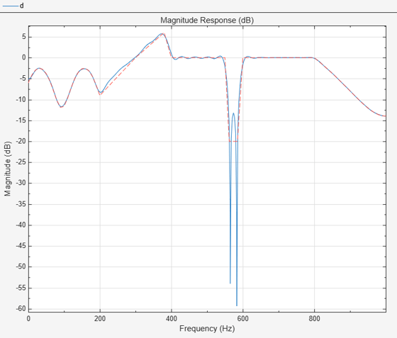
d = designfilt("arbmagfir", ...                      % Response type
    SampleRate=2000, ...                             % Sample rate
    FilterOrder=100, ...                             % Filter Order
    Frequencies=[0:10:200 300 380 ...                % Frequency constraints
        400 550 562 585 600 800:10:1000], ...
    Amplitudes=[(0.5+sin(2*pi*8*(0:0.01:0.2))/4) ... % Magnitude constraints
        1 2 1 1 -0.1 -0.1 1 0.2+20*(0.2:-0.01:0).^2], ...
    DesignMethod="freqsamp", ...                     % Design method
    Window={@kaiser,0.7});                           % Design method options
filterAnalyzer(d)
To design the filter using the Filter Designer app:
In the Response gallery of the Designer tab in the app toolstrip, select Arbitrary Response FIR.
Specify the filter using the options in the Filter Parameters table:
In Sample Rate, specify Frequency units as
Hzand Input sample rate (Hz) as2000.Under Filter Order, specify the Order mode as
Specifyand the Order as100.Under Response, specify the Frequencies and Amplitudes with these values:
Frequencies:
[0:10:200 300 380 400 550 562 585 600 800:10:1000]HzAmplitudes:
[(0.5+sin(2*pi*8*(0:0.01:0.2))/4) 1 2 1 1 -0.1 -0.1 1 0.2+20*(0.2:-0.01:0).^2].Under Algorithm, select
Frequency sampling.Under Algorithm Options, specify the Window as
Kaiserand the Window parameter as0.7.
In the Filter section of the Designer tab, click Update Filter.

Export code to create your digital filter. On the toolstrip, click Export and select
Generate MATLAB function>Digital Filter Object. The code appears in the editor.function designedFilter = arbrespfir1filt designedFilter = designfilt('arbmagfir', ... 'FilterOrder',100, ... 'Frequencies',[0:10:200 300 380 400 550 562 585 600 800:10:1000], ... 'Amplitudes',[(0.5+sin(2*pi*8*(0:0.01:0.2))/4) 1 2 1 1 -0.1 -0.1 ... 1 0.2+20*(0.2:-0.01:0).^2], ... 'SampleRate',2000,'Window',{@kaiser,0.7}); end
Parameters
Design Method
Specify the algorithm to design the filter. The available design methods correlate with the set of design specifications that you choose.
Design the filter using the Parks-McClellan algorithm. Equiripple filters have a frequency response that minimizes the maximum ripple magnitude over all bands.
designfilt Function | Filter Designer App |
|---|---|
Specify
| In the Algorithm section of the filter
parameters panel, set Design method to
|
The equiripple design method supports these design parameter combinations.
| Filter Order | Frequency Specifications | Magnitude Specifications | Design Method Options | DSP System Toolbox License Required |
|---|---|---|---|---|
| Arbitrary amplitudes | ||||
|
|
|
| |
|
|
|
| |
| N/A |
|
|
| ✓ |
|
|
|
| ✓ |
|
|
|
| ✓ |
| Arbitrary full responses in the magnitude-and-phase form | ||||
|
|
|
| ✓ |
|
|
|
| ✓ |
| Arbitrary full responses in the complex-valued form | ||||
|
|
|
| ✓ |
|
|
|
| ✓ |
Design the filter using the frequency-sampling algorithm. The method designs the filter by sampling the frequency response uniformly and taking the inverse Fourier transform.
designfilt Function | Filter Designer App |
|---|---|
Specify
| In the Algorithm section of the filter
parameters panel, set Design method to
|
The frequency-sampling design method supports these design parameter combinations.
| Filter Order | Frequency Specifications | Magnitude Specifications | Design Method Options | DSP System Toolbox License Required |
|---|---|---|---|---|
| Arbitrary amplitudes | ||||
|
|
|
| |
| Arbitrary full responses in the magnitude-and-phase form | ||||
|
|
|
| ✓ |
| Arbitrary full responses in the complex-valued form | ||||
|
|
|
| ✓ |
Design the filter using the least Pth-norm unconstrained optimization algorithm.
You must have a DSP System Toolbox license to use this design method.
designfilt Function | Filter Designer App |
|---|---|
Specify
| In the Algorithm section of the filter
parameters panel, set Design method to
|
The least Pth-norm method supports these design parameter combinations.
| Filter Order | Frequency Specifications | Magnitude Specifications | Design Method Options | DSP System Toolbox License Required |
|---|---|---|---|---|
| Arbitrary amplitudes | ||||
|
|
|
| ✓ |
|
|
|
| ✓ |
Design the filter using the least-squares algorithm. The method minimizes the discrepancy between a specified arbitrary piecewise-linear function and the filter’s magnitude response.
designfilt Function | Filter Designer App |
|---|---|
Specify | In the Algorithm section of the filter
parameters panel, set Design method to
|
The least-squares design method supports these design parameter combinations.
| Filter Order | Frequency Specifications | Magnitude Specifications | Design Method Options | DSP System Toolbox License Required |
|---|---|---|---|---|
| Arbitrary amplitudes | ||||
|
|
|
| |
|
|
|
| |
| Arbitrary full responses in the magnitude-and-phase form | ||||
|
|
|
| ✓ |
|
|
|
| ✓ |
| Arbitrary full responses in the complex-valued form | ||||
|
|
|
| ✓ |
|
|
|
| ✓ |
Sample Rate
Specify the filter sample rate as a positive scalar expressed in hertz.
designfilt Function | Filter Designer App |
|---|---|
| In the Sample Rate section of the filter parameters panel:
|
Filter Order
Specify the filter order N as a positive integer. Some design methods let you specify the order. Others generate minimum-order designs, which are the shortest filters that satisfy the specified constraints.
designfilt Function | Filter Designer App |
|---|---|
| In the Filter Order section of the filter parameters panel:
|
Specify the number of frequency bands as a positive integer not greater than 10. To design a multiband filter, set the number of bands to at least 2.
designfilt Function | Filter Designer App |
|---|---|
|
|
Frequency Specifications
Specify the frequencies associated with the arbitrary response as a vector. Use this specification to list the frequencies so that the filter response has the desired values.
If you specify a sample rate F s, the Nyquist frequency is Fs/2.
If you work with normalized frequencies, the Nyquist frequency is 1.
The frequencies must be monotonically increasing and lie within the Nyquist range. The first element of the vector must be either 0 or –Fs/2, and its last element must be Fs/2.
designfilt Function | Filter Designer App |
|---|---|
|
|
Specify the multiband frequencies associated with the arbitrary response as vectors. For each frequency band, use this specification to list the frequencies so that the filter response has the desired values.
If you specify a sample rate F s, the Nyquist frequency is Fs/2.
If you work with normalized frequencies, the Nyquist frequency is 1.
The frequencies must be monotonically increasing and lie within the Nyquist range. The first element of the vector must be either 0 or –Fs/2, and its last element must be Fs/2.
designfilt Function | Filter Designer App |
|---|---|
|
|
Magnitude Specifications
Specify the amplitudes associated with the arbitrary response as a vector with the same size of Frequencies. Use this specification to list the amplitudes (in linear units) so that the filter response has the desired values.
designfilt Function | Filter Designer App |
|---|---|
|
|
Specify the multiband amplitudes associated with the arbitrary response as vectors with the same size of Band Frequencies 1, ..., Band Frequencies N. For each frequency band, use this specification to list the amplitudes (in linear units) so that the filter response has the desired values.
designfilt Function | Filter Designer App |
|---|---|
|
|
Specify the multiband amplitudes associated with the arbitrary response as logical scalars. For each frequency band, use this specification to list whether to constrain the passband ripple of the filter response within the desired magnitude.
You can constrain up to NB – 1 bands, where NB is the Number of Bands of the filter. For each band that you constrain, you must specify a band ripple using Band Ripple 1, ..., Band Ripple N.
You must have a DSP System Toolbox license to use this specification.
designfilt Function | Filter Designer App |
|---|---|
|
|
Specify the multiband responses as vectors with the same size of Band Frequencies 1, ..., Band Frequencies N. For each frequency band, use this specification to list the frequency responses (complex values) so that the filter response has the desired values.
designfilt Function | Filter Designer App |
|---|---|
|
|
Specify the multiband magnitudes associated with the arbitrary response as vectors with the same size of Band Frequencies 1, ..., Band Frequencies N. For each frequency band, use this specification to list the magnitudes (in linear units) so that the filter response has the desired values.
designfilt Function | Filter Designer App |
|---|---|
| N/A |
|
Specify the multiband phases associated with the arbitrary response as vectors with the same size of Band Frequencies 1, ..., Band Frequencies N. For each frequency band, use this specification to list the phases (in radians) so that the filter response has the desired values.
designfilt Function | Filter Designer App |
|---|---|
| N/A |
|
Specify the multiband response passband ripples as positive scalars. For each constrained frequency band, use this specification to list the passband ripple (in linear units) up to which the amplitude response can fluctuate around the desired values.
You must specify as many passband ripples as constrained bands. To enable passband ripple constraint, use Band Constrained 1, ..., Band Constrained N.
You must have a DSP System Toolbox license to use this specification.
designfilt Function | Filter Designer App |
|---|---|
|
|
Specify the frequency response as a vector with the same size of Frequencies. Use this specification to list the frequency response (complex values) so that the filter response has the desired values.
designfilt Function | Filter Designer App |
|---|---|
|
|
Specify the magnitudes associated with the arbitrary response as a vector with the same size of Frequencies. Use this specification to list the magnitudes (complex absolute values in linear units) so that the filter response has the desired values.
designfilt Function | Filter Designer App |
|---|---|
| N/A |
|
Specify the phases associated with the arbitrary response as a vector with the same size of Frequencies. Use this specification to list the phases (in radians) so that the filter response has the desired values.
designfilt Function | Filter Designer App |
|---|---|
| N/A |
|
Design Method Options
Basic Options
Specify the optimization weights as a positive scalar or as a vector with the same size of Frequencies.
Weights are a way of specifying the relative importance of the passband ripple and the stopband attenuation in a filter design. By default, the passband and the stopbands are equally weighted, each with unit weight. By increasing a stopband weight, you can increase the attenuation of a stopband at the expense of increasing the passband ripple.
You must have a DSP System Toolbox license to use this option with some syntaxes.
designfilt Function | Filter Designer App |
|---|---|
|
|
Specify the multiband optimization weights as positive scalars or as vectors with the same size of Band Frequencies 1, ..., Band Frequencies N.
Weights are a way of specifying the relative importance of the passband ripple and the stopband attenuation in a filter design. By default, the passband and the stopbands are equally weighted, each with unit weight. By increasing a stopband weight, you can increase the attenuation of a stopband at the expense of increasing the passband ripple.
You must have a DSP System Toolbox license to use this option with some syntaxes.
designfilt Function | Filter Designer App |
|---|---|
|
|
Window used by the Frequency sampling algorithm, specified as one of these:
Hamming (@
hamming)Hann (@
hann)Kaiser (@
kaiser) — Specify the shape factor as a positive real scalar.Rectangular (@
rectwin)Chebyshev (@
chebwin) — Specify the sidelobe magnitude factor as a positive scalar in decibels.Bartlett (@
bartlett)Blackman (@
blackman)Flat top (@
flattopwin)Gaussian (@
gausswin) — To use a Gaussian window with a width factor α ≠ 2.5 in the Filter Designer app or the Design Filter Live Editor task, specify it as a custom window.Nuttall (@
nuttallwin)Triangular (@
triang)Custom — Specify a custom window as a vector of length N + 1, where N is the Filter Order. You can also specify the custom window as a function name or a function handle with N + 1 as first input. Additional inputs can be passed by specifying a cell array.
Example: hann(N+1) and
(1-cos(2*pi*(0:N)'/N))/2 both specify a Hann window to use with a
filter of order N.
Example: "hamming" specifies a Hamming window of the required
order.
Example: @hann specifies a Hann window of the required
order.
Example: {@kaiser,0.5} specifies a Kaiser window of the required
order with shape parameter 0.5.
designfilt Function | Filter Designer App |
|---|---|
|
|
Advanced Options
Multiband frequency points to force magnitude response to 0 dB for the Equiripple algorithm, specified as
[], positive scalars, or vectors. For each unconstrained
frequency band, use this design method option to list the frequency points at which to
force the magnitude response to 0 dB.
If you specify a sample rate F s , the Nyquist frequency is F s/2.
If you work with normalized frequencies, the Nyquist frequency is 1.
The frequencies must be monotonically increasing and lie within the Nyquist range. The first element of the vector must be either 0 or –Fs/2, and its last element must be Fs/2.
You must have a DSP System Toolbox license to use this option.
designfilt Function | Filter Designer App |
|---|---|
|
|
Density of the frequency grid used by the Equiripple, Frequency sampling, and Least Squares algorithms, specified as a positive scalar ≥ 10. The frequency grid has roughly (Density Factor × Filter Order) frequency points. Increasing the density factor results in filters that more closely approximate an equiripple filter but take longer to compute.
You must have a DSP System Toolbox license to use this option. This parameter is available only in the
designfilt function.
designfilt Function | Filter Designer App |
|---|---|
| N/A |
Initial estimate of the filter order for the Equiripple algorithm, specified as a positive integer.
You must have a DSP System Toolbox license to use this option. This parameter is available only in the
designfilt function.
designfilt Function | Filter Designer App |
|---|---|
|
|
Minimum order parity of an Equiripple design, specified as one of these options:
Any — The returned filter can have even or odd order, whichever is smaller.
Even — The returned filter has the smallest possible even order.
Odd — The returned filter has the smallest possible odd order. This option is available only for equiripple designs.
You must have a DSP System Toolbox license to use this option with the equiripple method.
designfilt Function | Filter Designer App |
|---|---|
|
|
Phase constraint on the Equiripple FIR filter, specified as one of these options:
Linear — Design a linear-phase equiripple FIR filter.
Minimum — Design a minimum-phase equiripple FIR filter.
Maximum — Design a maximum-phase equiripple FIR filter.
You must have a DSP System Toolbox license to use this option.
designfilt Function | Filter Designer App |
|---|---|
|
|
Option to set frequency grid as uniform for the Equiripple algorithm, specified as
true or false. Set this argument to
true to space the frequency grid points uniformly in the
frequency bands of interest. Control the density of the uniform grid with the Density Factor option.
You must have a DSP System Toolbox license to use this option.
designfilt Function | Filter Designer App |
|---|---|
| N/A |
More About
See Also
Apps
Functions
Live Editor Tasks
MATLAB Command
You clicked a link that corresponds to this MATLAB command:
Run the command by entering it in the MATLAB Command Window. Web browsers do not support MATLAB commands.
Seleziona un sito web
Seleziona un sito web per visualizzare contenuto tradotto dove disponibile e vedere eventi e offerte locali. In base alla tua area geografica, ti consigliamo di selezionare: .
Puoi anche selezionare un sito web dal seguente elenco:
Come ottenere le migliori prestazioni del sito
Per ottenere le migliori prestazioni del sito, seleziona il sito cinese (in cinese o in inglese). I siti MathWorks per gli altri paesi non sono ottimizzati per essere visitati dalla tua area geografica.
Americhe
- América Latina (Español)
- Canada (English)
- United States (English)
Europa
- Belgium (English)
- Denmark (English)
- Deutschland (Deutsch)
- España (Español)
- Finland (English)
- France (Français)
- Ireland (English)
- Italia (Italiano)
- Luxembourg (English)
- Netherlands (English)
- Norway (English)
- Österreich (Deutsch)
- Portugal (English)
- Sweden (English)
- Switzerland
- United Kingdom (English)