Contenuto principale

filterBuilder

R2026b

(To be removed) Interactive filter design

filterBuilder warns and will be removed in a future release. Use the Filter Designer app or the designfilt function with no input arguments instead.

Syntax

filterBuilder(h)
filterBuilder('response')

Description

filterBuilder starts an interactive tool for building filters. It relies on the fdesign object-object oriented filter design paradigm, and is intended to reduce development time during the filter design process. filterBuilder uses a specification-centered approach to find the best algorithm for the desired response.

Note

You must have the Signal Processing Toolbox™ installed to use fdesign and filterBuilder. Some of the features described below may be unavailable if your installation does not additionally include the DSP System Toolbox™. You can verify the presence of both toolboxes by typing ver at the command prompt.

To use filterBuilder, enter filterBuilder at the MATLAB® command line using one of three approaches:

  • Simply enter filterBuilder. MATLAB opens a dialog box for you to select a filter response type. After you select a filter response type, filterBuilder launches the appropriate filter design dialog box.

  • Enter filterBuilder(h), where h is an existing filter object. For example, if h is a bandpass filter, filterBuilder(h) opens the bandpass filter design dialog box. The h object must have been created using filterBuilder or using fdesign.

    Note

    You must have the DSP System Toolbox software to create and import filter System objects.

  • Enter filterBuilder('response') to replace response with a response method from the following table. MATLAB opens a filter design dialog box that corresponds to the specified response.

Note

You must have the DSP System Toolbox software to implement a number of the filter designs listed in the following table. If you only have the Signal Processing Toolbox software, you can design a limited set of the following filter-response types.

Response MethodDescription of Resulting Filter Design
arbgrpdelayArbitrary group delay filter design
arbmagArbitrary magnitude filter design
arbmagnphaseArbitrary response filter (magnitude and phase)
bandpass or bpBandpass filter
bandstop or bsBandstop filter
cicCIC filter
ciccompCIC compensator
combComb filter
diffDifferentiator filter
fracdelayFractional delay filter
halfband or hbHalfband filter
highpass or hpHighpass filter
hilbHilbert filter
isinc,
isinclp, or
isinchp
Inverse sinc lowpass or highpass filter
lowpass or lpLowpass filter (default)
notchNotch filter
nyquistNyquist filter
octaveOctave filter
peakPeak filter

Note

Because they do not change the filter structure, the magnitude specifications and design method are tunable when using filterBuilder.

Filter Builder Design Panes

Main Design Pane

The main pane of Filter Builder varies depending on the filter response type, but the basic structure is the same. The following figure shows the basic layout of the dialog box.

Main pane

As you choose the response for the filter, the available options and design parameters displayed in the dialog box change. This display allows you to focus only on parameters that make sense in the context of your filter design.

Every filter design dialog box includes the options displayed at the top of the dialog box, shown in the following figure.

Save variables UI field

  • Save variable as — When you click Apply to apply your changes or OK to close this dialog box, filterBuilder saves the current filter to your MATLAB workspace as a filter object with the name you enter.

  • View Filter Response — Displays the magnitude response for the current filter specifications and design method. If you specify the input sample rate, the magnitude response is a function of frequency in Hz. If you do not specify the input sample rate, the magnitude response is a function of normalized frequency in rad/sample.

Note

The filterBuilder dialog box includes an Apply option. Each time you click Apply, filterBuilder writes the modified filter to your MATLAB workspace. This modified filter has the variable name you assign in Save variable as. To apply changes without overwriting the variable in you workspace, change the variable name in Save variable as before you click Apply.

There are three tabs in the Filter Builder dialog box, containing three panes: Main, Data Types, and Code Generation. The first pane changes according to the filter being designed. The last two panes are the same for all filters. These panes are discussed in the following sections.

Data Types Pane

The second tab in the Filter Builder dialog box is shown in the following figure.

Data types pane

The Arithmetic drop down box allows the choice of Double precision, Single precision, or Fixed point. Some of these options may be unavailable depending on the filter parameters. The following table describes these options.

Arithmetic List EntryEffect on the Filter
Double precisionAll filtering operations and coefficients use double-precision, floating-point representations and math. When you use filterBuilder to create a filter, double precision is the default value for the Arithmetic property.
Single precisionAll filtering operations and coefficients use single-precision floating-point representations and math.
Fixed pointThis entry applies selected default values, typically used on many digital processors, for the properties in the fixed-point filter. These properties include coefficient word lengths, fraction lengths, and various operating modes. This setting allows signed fixed data types only. Fixed-point filter design with filterBuilder is available only when you install Fixed-Point Designer™ software along with DSP System Toolbox software.

The following figure shows the Data Types pane after you select Fixed point for Arithmetic and set Filter internals to Specify precision. This figure shows the Data Types pane for the case where the Use a System object to implement filter check box is not selected in the Main pane.

Data types pane

When you select Use a System object to implement filter check box in the Main pane, the Data Types pane appears as below:

Data types pane

Not all parameters described in the following section apply to all filters. For example, FIR filters do not have the Section input and Section output parameters.

Input signal

Specify the format the filter applies to data to be filtered. For all cases, filterBuilder implements filters that use binary point scaling and signed input. You set the word length and fraction length as needed.

Coefficients

Choose how you specify the word length and the fraction length of the filter numerator and denominator coefficients:

  • Specify word length enables you to enter the word length of the coefficients in bits. In this mode, filterBuilder automatically sets the fraction length of the coefficients to the binary-point only scaling that provides the best possible precision for the value and word length of the coefficients.

  • Binary point scaling enables you to enter the word length and the fraction length of the coefficients in bits. If applicable, enter separate fraction lengths for the numerator and denominator coefficients.

  • The filter coefficients do not obey the Rounding mode and Overflow mode parameters that are available when you select Specify precision from the Filter internals list. Coefficients are always saturated and rounded to Nearest.

Section Input

Choose how you specify the word length and the fraction length of the fixed-point data type going into each section of an SOS filter. This parameter is visible only when the selected filter structure is IIR and SOS.

  • Binary point scaling enables you to enter the word and fraction lengths of the section input in bits.

  • Specify word length enables you to enter the word lengths in bits.

Section Output

Choose how you specify the word length and the fraction length of the fixed-point data type coming out of each section of an SOS filter. This parameter is visible only when the selected filter structure is IIR and SOS.

  • Binary point scaling enables you to enter the word and fraction lengths of the section output in bits.

  • Specify word length enables you to enter the output word lengths in bits.

State

Contains the filter states before, during, and after filter operations. States act as filter memory between filtering runs or sessions. Use this parameter to specify how to designate the state word and fraction lengths. This parameter is not visible for direct form and direct form I filter structures because filterBuilder deduces the state directly from the input format. States always use signed representation:

  • Binary point scaling enables you to enter the word length and the fraction length of the accumulator in bits.

  • Specify precision enables you to enter the word length and fraction length in bits (if available).

Product

Determines how the filter handles the output of product operations. Choose from the following options:

  • Full precision — Maintain full precision in the result.

  • Keep LSB — Keep the least significant bit in the result when you need to shorten the data words.

  • Specify Precision — Enables you to set the precision (the fraction length) used by the output from the multiplies.

Filter internals

Specify how the fixed-point filter performs arithmetic operations within the filter. The affected filter portions are filter products, sums, states, and output. Select one of these options:

  • Full precision — Specifies that the filter maintains full precision in all calculations for products, output, and in the accumulator.

  • Specify precision — Set the word and fraction lengths applied to the results of product operations, the filter output, and the accumulator. Selecting this option enables the word and fraction length controls.

Signed

Selecting this option directs the filter to use signed representations for the filter coefficients.

Word length

Sets the word length for the associated filter parameter in bits.

Fraction length

Sets the fraction length for the associate filter parameter in bits.

Accum

Use this parameter to specify how you would like to designate the accumulator word and fraction lengths.

Determines how the accumulator outputs stored values. Choose from the following options:

  • Full precision — Maintain full precision in the accumulator.

  • Keep MSB — Keep the most significant bit in the accumulator.

  • Keep LSB — Keep the least significant bit in the accumulator when you need to shorten the data words.

  • Specify Precision — Enables you to set the precision (the fraction length) used by the accumulator.

Output

Sets the mode the filter uses to scale the output data after filtering. You have the following choices:

  • Avoid Overflow — Set the output data fraction length to avoid causing the data to overflow. Avoid overflow is considered the conservative setting because it is independent of the input data values and range.

  • Best Precision — Set the output data fraction length to maximize the precision in the output data.

  • Specify Precision — Set the fraction length used by the filtered data.

Fixed-point operational parameters

Parameters in this group control how the filter rounds fixed-point values and how it treats values that overflow.

Rounding mode

Sets the mode the filter uses to quantize numeric values when the values lie between representable values for the data format (word and fraction lengths).

  • ceil — Round toward positive infinity.

  • convergent — Round to the closest representable integer. Ties round to the nearest even stored integer. This is the least biased of the methods available in this software.

  • zero/fix — Round toward zero.

  • floor — Round toward negative infinity.

  • nearest — Round toward nearest. Ties round toward positive infinity.

  • round — Round toward nearest. Ties round toward negative infinity for negative numbers, and toward positive infinity for positive numbers.

The choice you make affects everything except coefficient values and input data which always round. In most cases, products do not overflow—they maintain full precision.

Overflow mode

Sets the mode the filter uses to respond to overflow conditions in fixed-point arithmetic. Choose from the following options:

  • Saturate — Limit the output to the largest positive or negative representable value.

  • Wrap — Set overflowing values to the nearest representable value using modular arithmetic.

The choice you make affects everything except coefficient values and input data which always round. In most cases, products do not overflow—they maintain full precision.

Cast before sum

Specifies whether to cast numeric data to the appropriate accumulator format before performing sum operations. Selecting Cast before sum ensures that the results of the affected sum operations match most closely the results found on most digital signal processors. Performing the cast operation before the summation adds one or two additional quantization operations that can add error sources to your filter results.

If you clear Cast before sum, the filter prevents the addends from being cast to the sum format before the addition operation. Choose this setting to get the most accurate results from summations without considering the hardware your filter might use. The input format referenced by Cast before sum depends on the filter structure you are using.

The effect of clearing or selecting Cast before sum is as follows:

  • Cleared — Configures filter summation operations to retain the addends in the format carried from the previous operation.

  • Selected — Configures filter summation operations to convert the input format of the addends to match the summation output format before performing the summation operation. Usually, selecting Cast before sum generates results from the summation that more closely match those found from digital signal processors.

Code Generation Pane

The code generation pane contains options for various implementations of the completed filter design. Depending on your installation, you can generate MATLAB code or create or update a Simulink® model from the designed filter. The following section explains these options.
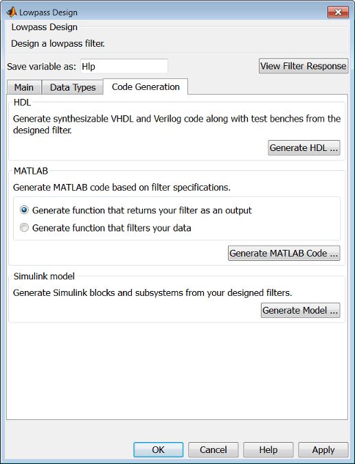
Code generation pane

MATLAB

Generate MATLAB code based on filter specifications

  • Generate function that returns your filter as an output

    Selecting this option generates a function that designs a filter object using fdesign.

  • Generate function that filters your data

    Selecting this option generates a function that takes data as input, and outputs data filtered with the designed filter. The data type of the filter output is set according to the data type settings in the Data Types pane.

Clicking on the Generate MATLAB code button, brings up a Save File dialog box. Specify the file name and location, and save. The filter is now contained in an editable file.

Simulink Model

Generate Simulink blocks and subsystems from your designed filters

When you click Generate Model, the filter builder generates Simulink blocks and subsystems from your designed filters.

Clicking on the Generate Model button opens the Export to Simulink dialog box.

Export to Simulink dialog

  • Block Name — The name for the new subsystem block, set to Filter by default.

  • DestinationCurrent saves the generated model to the current Simulink model. New creates a new model to contain the generated block. User Defined creates a new model or subsystem at the location specified in User Defined.

  • Overwrite generated 'Filter' block — Overwrites an existing block with the name specified in Block Name. Clear this check box to create a new block with the same name.

  • Build model using basic elements — Builds the model using only basic blocks.

  • Optimize for zero gains — Removes all zero-gain blocks from the model.

  • Optimize for unity gains — Replaces all unity gains with direct connections.

  • Optimize for negative gains — Removes all negative unity gain blocks, and changes sign at the nearest summation block.

  • Optimize delay chains — Replaces delay chains made up of n unit delays with a single delay by n.

  • Optimize for unity scale values — Removes all scale value multiplications by 1 from the filter structure.

  • Input processing — Specify how the generated filter block or subsystem block processes the input. Depending on the type of filter you are designing, one or both of the following options may be available:

    • Columns as channels (frame based) — The block treats each column of the input as a separate channel.

    • Elements as channels (sample based) — The block treats each element of the input as a separate channel.

    For more information about sample-based and frame-based processing, see Sample- and Frame-Based Concepts (DSP System Toolbox).

  • Realize Model — Builds the model with the set parameters.

When the Use a System object to implement filter check box is selected in the Main pane, the Generate Model button in the Simulink model panel is disabled under the following conditions:

  • Select Filter response as Comb and Arithmetic on the Data Types pane as Fixed point.

  • Select Filter response as Arbitrary Response, Impulse response as IIR, set Specify response as to either Magnitudes and phases or Frequency response, and Arithmetic on the Data Types pane as Fixed point.

These settings design a dsp.IIRFilter System object™ with fixed point arithmetic. Generating a Simulink model for fixed point dsp.IIRFilter object is not supported.

Filter Responses

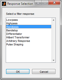
Select your filter response from the filterBuilder Response Selection main menu.

If you have the DSP System Toolbox software, the following Response Selection menu appears.

Filter responses

Select your desired filter response from the menu and design your filter.

The following sections describe the options available for each response type.

Arbitrary Response Filter Design — Main Pane

Parameters in this group enable you to specify your filter format, such as the impulse response and the filter order.

Impulse response

This dialog only applies if you have the DSP System Toolbox software. Select either FIR or IIR from the drop down list, where FIR is the default impulse response. When you choose an impulse response, the design methods and structures you can use to implement your filter change accordingly. Arbitrary group delay designs are only available if Impulse response is IIR. Without the DSP System Toolbox, the only available arbitrary response filter design is FIR.

Order mode

This dialog only applies if you have the DSP System Toolbox software. Choose Minimum or Specify. Choosing Specify enables the Order dialog.

Order

This dialog only applies when Order mode is Specify. For an FIR design, specify the filter order. For an IIR design, you can specify an equal order for the numerator and denominator, or you can specify different numerator and denominator orders. The default is equal orders. To specify a different denominator order, check the Denominator order box. Because the Signal Processing Toolbox only supports FIR arbitrary-magnitude filters, you do not have the option to specify a denominator order.

Denominator order

Select the check box and enter the denominator order. This option is enabled only if IIR is selected for Impulse response.

Filter type

This dialog only applies if you have the DSP System Toolbox software and is only available for FIR filters. Select Single-rate, Decimator, Interpolator, or Sample-rate converter. Your choice determines the type of filter as well as the design methods and structures that are available to implement your filter. By default, filterBuilder specifies single-rate filters.

  • Selecting Decimator or Interpolator activates the Decimation Factor or the Interpolation Factor options respectively.

  • Selecting Sample-rate converter activates both factors.

When you design either a decimator or interpolator, the resulting filter is a bandpass filter that either decimates or interpolates your input signal.

Decimation Factor

Enter the decimation factor. This option is enabled only if the Filter type is set to Decimator or Sample-rate converter. The default factor value is 2 for Decimator and 3 for Sample-rate converter.

Interpolation Factor

Enter the decimation factor. This option is enabled only if the Filter type is set to Interpolator or Sample-rate converter. The default factor value is 2.

Number of Bands

Select the number of bands in the filter. Multiband design is available for both FIR and IIR filters.

Specify response as:

Specify the response as Amplitudes, Magnitudes and phase, Frequency response, or Group delay. Amplitudes is the only option if you do not have the DSP System Toolbox software. Group delay is only available for IIR designs.

Frequency units

Specify frequency units as either Normalized, Hz, kHz, MHz, or GHz.

Input sample rate

Enter the input sample rate in the units specified in the Frequency units drop-down box. This option is enabled when Frequency units is set to an option in hertz.

These properties are modified automatically depending on the response chosen in the Specify response as drop-down box. Two or three columns are presented for input. The first column is always Frequencies. The other columns are either Amplitudes, Magnitudes, Phases, or Frequency Response. Enter the corresponding vectors of values for each column.

  • Frequencies and Amplitudes — These columns are presented for input if you select Amplitudes in the Specify response as drop-down box.

  • Frequencies, Magnitudes, and Phases — These columns are presented for input if the response chosen in the Specify response as drop-down box is Magnitudes and phases.

  • Frequencies and Frequency response — These columns are presented for input if the response chosen in the Specify response as drop-down box is Frequency response.

The options for each design are specific for each design method. In the arbitrary response design, the available options also depend on the Response specifications. This section does not present all of the available options for all designs and design methods.

Design Method

Select the design method for the filter. Different methods are enabled depending on the defining parameters entered in the previous sections.

Design Options

  • Window — Valid when the Design method is Frequency Sampling. Replace the square brackets with the name of a window function or function handle. For example, 'hamming' or @hamming. If the window function takes parameters other than the length, use a cell array. For example, {'kaiser',3.5} or {@chebwin,60}.

  • Density factor — Valid when the Design method is equiripple. Density factor controls the density of the frequency grid over which the design method optimization evaluates your filter response function. The number of equally spaced points in the grid is the value you enter for Density factor times (filter order + 1).

    Increasing the value creates a filter that more closely approximates an ideal equiripple filter but increases the time required to design the filter. The default value of 16 represents a reasonable trade between the accurate approximation to the ideal filter and the time to design the filter.

    The default changes to 20 for an IIR arbitrary group delay design.

  • Phase constraint — Valid when the Design method is equiripple, you have the DSP System Toolbox installed, and Specify response as is set to Amplitudes. Choose one of Linear, Minimum, or Maximum.

  • Weights — Uses the weights in Weights to weight the error for a single-band design. If you have multiple frequency bands, the Weights design option changes to B1 Weights, B2 Weights to designate the separate bands. Use Bi Weights to specify weights for the i-th band. The Bi Weights design option is only available when you specify the i-th band as an unconstrained.

  • Bi forced frequency point — This option is only available in a multi-band constrained equiripple design when Specify response as is Amplitudes. Bi forced frequency point is the frequency point in the i-th band at which the response is forced to be zero. The index i corresponds to the frequency bands in Band properties. For example, if you specify two bands in Band properties, you have B1 forced frequency point and B2 forced frequency point.

  • Norm — Valid only for IIR arbitrary group delay designs. Norm is the norm used in the optimization. The default value is 128, which essentially equals the L-infinity norm. The norm must be even.

  • Max pole radius — Valid only for IIR arbitrary group delay designs. Constrains the maximum pole radius. The default is 0.999999. Reducing the Max pole radius can produce a transfer function more resistant to quantization.

  • Init norm — Valid only for IIR arbitrary group delay designs. The initial norm used in the optimization. The default initial norm is 2.

  • Init numerator — Specifies an initial estimate of the filter numerator coefficients.

  • Init denominator — Specifies an initial estimate of the filter denominator coefficients. This may be useful in difficult optimization problems. In allpass filters, you only have to specify either the denominator or numerator coefficients. If you specify the denominator coefficients, you can obtain the numerator coefficients.

Structure

Select the structure for the filter. The available filter structures depend on the parameters you select for your filter.

Use a System object to implement filter

This check box appears when you set Filter type to Single-rate. Selecting this check box gives you the choice of using a System object to implement the filter. By default, this check box is cleared.

This check box no longer appears when you set Filter type to Interpolator, Decimator, or Sample-rate converter. The filter builder always implements the filter as a System object.

Bandpass Filter Design — Main Pane

Parameters in this group enable you to specify your filter format, such as the impulse response and the filter order.

Impulse response

Select FIR or IIR from the drop-down list, where FIR is the default impulse response. When you choose an impulse response, the design methods and structures you can use to implement your filter change accordingly.

Note

The design methods and structures for FIR filters are not the same as the methods and structures for IIR filters.

Order mode

Select Minimum (the default) or Specify from the drop-down box. Selecting Specify enables the Order option so you can enter the filter order.

If you have the DSP System Toolbox software installed, you can specify IIR filters with different numerator and denominator orders. The default is equal orders. To specify a different denominator order, check the Denominator order box.

Filter type — This dialog only applies if you have the DSP System Toolbox software.

Select Single-rate, Decimator, Interpolator, or Sample-rate converter. Your choice determines the type of filter as well as the design methods and structures that are available to implement your filter. By default, filterBuilder specifies single-rate filters.

  • Selecting Decimator or Interpolator activates the Decimation Factor or the Interpolation Factor options respectively.

  • Selecting Sample-rate converter activates both factors.

Order

Enter the filter order. This option is enabled only if you select Specify for Order mode.

Decimation Factor

Enter the decimation factor. This option is enabled only if the Filter type is set to Decimator or Sample-rate converter. The default factor value is 2.

Interpolation Factor

Enter the decimation factor. This option is enabled only if the Filter type is set to Interpolator or Sample-rate converter. The default factor value is 2.

The parameters in this group allow you to specify your filter response curve. Graphically, the filter specifications look similar to those shown in the following figure.

Frequency specifications

In the figure, regions between specification values such as Stopband frequency 1 (Fstop1) and Passband frequency 1 (Fpass1) represent transition regions where the filter response is not explicitly defined.

Frequency constraints

Select the filter features to use to define the frequency response characteristics. This dialog applies only when Order mode is Specify.

  • Passband and stopband frequencies — Define the filter by specifying the frequencies for the edges for the stop- and passbands.

  • Passband frequency — Define the filter by specifying frequencies for the edges of the passband.

  • Stopband frequency — Define the filter by specifying frequencies for the edges of the stopbands.

  • Half power (3dB) frequency — Define the filter response by specifying the locations of the 3 dB points (IIR filters). The 3 dB point is the frequency for the point 3 dB below the passband value.

  • Half power (3dB) frequencies and passband width — Define the filter by specifying frequencies for the 3 dB points in the filter response and the width of the passband. (IIR filters)

  • Half power (3dB) frequencies and stopband width — Define the filter by specifying frequencies for the 3 dB points in the filter response and the width of the stopband. (IIR filters)

  • Cutoff (6dB) frequency — Define the filter response by specifying the locations of the 6 dB points. The 6 dB point is the frequency for the point 6 dB below the passband value. (FIR filters)

Frequency units

Use this parameter to specify whether your frequency settings are normalized or in absolute frequency. Select Normalized (0 to 1) to enter frequencies in normalized form. This behavior is the default. To enter frequencies in hertz, select one of the frequency units from the drop-down list—Hz, kHz, MHz, or GHz. Selecting one of the unit options enables the Input sample rate parameter.

Input sample rate

Fs, specified in the units you selected for Frequency units, defines the sample rate at the filter input. When you provide an input sample rate, all frequencies in the specifications are in the selected units as well. This parameter is available when you select one of the frequency options from the Frequency units list.

Stopband frequency 1

Enter the frequency at the edge of the end of the first stopband. Specify the value in either normalized frequency units or the absolute units you select in Frequency units.

Passband frequency 1

Enter the frequency at the edge of the start of the passband. Specify the value in either normalized frequency units or the absolute units you select Frequency units.

Passband frequency 2

Enter the frequency at the edge of the end of the passband. Specify the value in either normalized frequency units or the absolute units you select Frequency units.

Stopband frequency 2

Enter the frequency at the edge of the start of the second stopband. Specify the value in either normalized frequency units or the absolute units you select Frequency units.

The parameters in this group let you specify the filter response in the passbands and stopbands.

Magnitude constraints

Specify as Unconstrained or Constrained bands. You must have the DSP System Toolbox software to select Constrained bands. Selecting Constrained bands enables dialogs for both stopbands and the passband: Stopband attenuation 1, Stopband attenuation 2, and Passband ripple. You cannot specify constraints for all three bands simultaneously.

Setting Magnitude constraints to Constrained bands enables the Wstop and Wpass options under Design options.

Magnitude units

Specify the units for any parameter you provide in magnitude specifications. Select one of the following options from the drop-down list.

  • Linear — Specify the magnitude in linear units.

  • dB — Specify the magnitude in dB (decibels). This is the default setting.

  • Squared — Specify the magnitude in squared units.

Stopband attenuation 1

Enter the filter attenuation in the first stopband in the units you choose for Magnitude units, either linear or decibels.

Passband ripple

Enter the filter ripple allowed in the passband in the units you choose for Magnitude units, either linear or decibels.

Stopband attenuation 2

Enter the filter attenuation in the second stopband in the units you choose for Magnitude units, either linear or decibels.

The parameters in this group allow you to specify the design method and structure that filterBuilder uses to implement your filter.

Design Method

Lists the design methods available for the frequency and magnitude specifications you entered. When you change the specifications for a filter, such as changing the impulse response, the methods available to design filters changes as well. The default IIR design method is usually Butterworth, and the default FIR method is equiripple.

Scale SOS filter coefficients to reduce chance of overflow

Selecting this parameter directs the design to scale the filter coefficients to reduce the chances that the inputs or calculations in the filter overflow and exceed the representable range of the filter. Clearing this option removes the scaling. This parameter applies only to IIR filters.

Design Options

The options for each design are specific for each design method. This section does not present all of the available options for all designs and design methods. There are many more that you encounter as you select different design methods and filter specifications. The following options represent some of the most common ones available.

Density factor

Density factor controls the density of the frequency grid over which the design method optimization evaluates your filter response function. The number of equally spaced points in the grid is the value you enter for Density factor times (filter order + 1).

Increasing the value creates a filter that more closely approximates an ideal equiripple filter but increases the time required to design the filter. The default value of 16 represents a reasonable trade between the accurate approximation to the ideal filter and the time to design the filter.

Phase constraint

Valid when the Design method is equiripple and you have the DSP System Toolbox installed. Choose one of Linear, Minimum, or Maximum.

Minimum order

This option only applies when you have the DSP System Toolbox software and Order mode is Minimum.

Select Any (default), Even, or Odd. Selecting Even or Odd forces the minimum-order design to be an even or odd order.

Wstop1

Weight for the first stopband.

Wpass

Passband weight.

Wstop2

Weight for the second stopband.

Max pole radius

Valid only for IIR designs. Constrains the maximum pole radius. The default is 1. Reducing the max pole radius can produce a transfer function more resistant to quantization.

Init norm

Valid only for IIR designs. The initial norm used in the optimization. The default initial norm is 2.

Init numerator

Specifies an initial estimate of the filter numerator coefficients. This may be useful in difficult optimization problems.

Init denominator

Specifies an initial estimate of the filter denominator coefficients. This may be useful in difficult optimization problems.

Structure

For the filter specifications and design method you select, this parameter lists the filter structures available to implement your filter. By default, FIR filters use direct-form structure, and IIR filters use direct-form II filters with SOS.

Use a System object to implement filter

This check box appears when you set Filter type to Single-rate. Selecting this check box gives you the choice of using a System object to implement the filter. By default, this check box is cleared.

This check box no longer appears when you set Filter type to Interpolator, Decimator, or Sample-rate converter. The filter builder always implements the filter as a System object.

Bandstop Filter Design — Main Pane

Parameters in this group enable you to specify your filter format, such as the impulse response and the filter order.

Impulse response

Select FIR or IIR from the drop-down list, where FIR is the default impulse response. When you choose an impulse response, the design methods and structures you can use to implement your filter change accordingly.

Note

The design methods and structures for FIR filters are not the same as the methods and structures for IIR filters.

Order mode

Select Minimum (the default) or Specify from the drop-down list. Selecting Specify enables the Order option so you can enter the filter order.

If you have the DSP System Toolbox software installed, you can specify IIR filters with different numerator and denominator orders. The default is equal orders. To specify a different denominator order, check the Denominator order box.

Filter type

Select Single-rate, Decimator, Interpolator, or Sample-rate converter. Your choice determines the type of filter as well as the design methods and structures that are available to implement your filter. By default, filterBuilder specifies single-rate filters.

  • Selecting Decimator or Interpolator activates the Decimation Factor or the Interpolation Factor options respectively.

  • Selecting Sample-rate converter activates both factors.

When you design either a decimator or an interpolator, the resulting filter is a bandpass filter that either decimates or interpolates your input signal.

Order

Enter the filter order. This option is enabled only if Specify was selected for Order mode.

Decimation Factor

Enter the decimation factor. This option is enabled only if the Filter type is set to Decimator or Sample-rate converter. The default factor value is 2.

Interpolation Factor

Enter the decimation factor. This option is enabled only if the Filter type is set to Interpolator or Sample-rate converter. The default factor value is 2.

The parameters in this group allow you to specify your filter response curve. Graphically, the filter specifications look similar to those shown in the following figure.

Frequency specifications

Frequency constraints

Select the filter features to use to define the frequency response characteristics. This dialog applies only when Order mode is Specify.

  • Passband and stopband frequencies — Define the filter by specifying the frequencies for the edges for the stop- and passbands.

  • Passband frequency — Define the filter by specifying frequencies for the edges of the passband.

  • Stopband frequency — Define the filter by specifying frequencies for the edges of the stopbands.

  • Half power (3dB) frequency — Define the filter response by specifying the locations of the 3 dB points (IIR filters). The 3 dB point is the frequency for the point 3 dB point below the passband value.

  • Half power (3dB) frequencies and passband width — Define the filter by specifying frequencies for the 3 dB points in the filter response and the width of the passband (IIR filters).

  • Half power (3dB) frequencies and stopband width — Define the filter by specifying frequencies for the 3 dB points in the filter response and the width of the stopband (IIR filters).

  • Cutoff (6dB) frequency — Define the filter response by specifying the locations of the 6 dB points (FIR filters). The 6 dB point is the frequency for the point 6 dB point below the passband value.

Frequency units

Use this parameter to specify whether your frequency settings are normalized or in absolute frequency. Select Normalized (0 to 1) to enter frequencies in normalized form. This behavior is the default. To enter frequencies in absolute values, select one of the frequency units from the drop-down list—Hz, kHz, MHz, or GHz. Selecting one of the unit options enables the Input sample rate parameter.

Input sample rate

Fs, specified in the units you selected for Frequency units, defines the sample rate at the filter input. When you provide an input sample rate, all frequencies in the specifications are in the selected units as well. This parameter is available when you select one of the frequency options from the Frequency units list.

Output sample rate

When you design an interpolator, Fs represents the sample rate at the filter output rather than the filter input. This option is available only when you set Filter type is interpolator.

Passband frequency 1

Enter the frequency at the edge of the end of the first passband. Specify the value in either normalized frequency units or the absolute units you select in Frequency units.

Stopband frequency 1

Enter the frequency at the edge of the start of the stopband. Specify the value in either normalized frequency units or the absolute units you select Frequency units.

Stopband frequency 2

Enter the frequency at the edge of the end of the stopband. Specify the value in either normalized frequency units or the absolute units you select Frequency units.

Passband frequency 2

Enter the frequency at the edge of the start of the second passband. Specify the value in either normalized frequency units or the absolute units you select Frequency units.

The parameters in this group let you specify the filter response in the passbands and stopbands.

Magnitude constraints

Specify as Unconstrained or Constrained bands. You must have the DSP System Toolbox software to select Constrained bands. Selecting Constrained bands enables dialogs for both passbands and the stopband: Passband ripple 1, Passband ripple 2, and Stopband attenuation. You cannot specify constraints for all three bands simultaneously.

Setting Magnitude constraints to Constrained bands enables the Wstop and Wpass options under Design options.

Magnitude units

Specify the units for any parameter you provide in magnitude specifications. Select one of the following options from the drop-down list.

  • Linear — Specify the magnitude in linear units.

  • dB — Specify the magnitude in decibels (default).

  • Squared — Specify the magnitude in squared units.

Passband ripple 1

Enter the filter ripple allowed in the first passband in the units you choose for Magnitude units, either linear or decibels.

Stopband attenuation

Enter the filter attenuation in the stopband in the units you choose for Magnitude units, either linear or decibels

Passband ripple 2

Enter the filter ripple allowed in the second passband in the units you choose for Magnitude units, either linear or decibels

The parameters in this group allow you to specify the design method and structure that filterBuilder uses to implement your filter.

Design Method

Lists the design methods available for the frequency and magnitude specifications you entered. When you change the specifications for a filter, such as changing the impulse response, the methods available to design filters changes as well. The default IIR design method is usually Butterworth, and the default FIR method is equiripple.

Scale SOS filter coefficients to reduce chance of overflow

Selecting this parameter directs the design to scale the filter coefficients to reduce the chances that the inputs or calculations in the filter overflow and exceed the representable range of the filter. Clearing this option removes the scaling. This parameter applies only to IIR filters.

Design Options

The options for each design are specific for each design method. This section does not present all of the available options for all designs and design methods. There are many more that you encounter as you select different design methods and filter specifications. The following options represent some of the most common ones available.

Density factor

Density factor controls the density of the frequency grid over which the design method optimization evaluates your filter response function. The number of equally spaced points in the grid is the value you enter for Density factor times (filter order + 1).

Increasing the value creates a filter that more closely approximates an ideal equiripple filter but increases the time required to design the filter. The default value of 16 represents a reasonable trade between the accurate approximation to the ideal filter and the time to design the filter.

Phase constraint

Valid when the Design method is equiripple and you have the DSP System Toolbox installed. Choose one of Linear, Minimum, or Maximum.

Minimum order

This option only applies when you have the DSP System Toolbox software and Order mode is Minimum.

Select Any (default), Even, or Odd. Selecting Even or Odd forces the minimum-order design to be an even or odd order.

Wpass1

Weight for the first passband.

Wstop

Stopband weight.

Wpass2

Weight for the second passband.

Match exactly

Specifies that the resulting filter design matches either the passband or stopband or both bands when you select passband or stopband.

Max pole radius

Valid only for IIR designs. Constrains the maximum pole radius. The default is 1. Reducing the max pole radius can produce a transfer function more resistant to quantization.

Init norm

Valid only for IIR designs. The initial norm used in the optimization. The default initial norm is 2.

Init numerator

Specifies an initial estimate of the filter numerator coefficients. This may be useful in difficult optimization problems.

Init denominator

Specifies an initial estimate of the filter denominator coefficients. This may be useful in difficult optimization problems.

Structure

For the filter specifications and design method you select, this parameter lists the filter structures available to implement your filter. By default, FIR filters use direct-form structure, and IIR filters use direct-form II filters with SOS.

Use a System object to implement filter

This check box appears when you set Filter type to Single-rate. Selecting this check box gives you the choice of using a System object to implement the filter. By default, this check box is cleared.

This check box no longer appears when you set Filter type to Interpolator, Decimator, or Sample-rate converter. The filter builder always implements the filter as a System object.

CIC Filter Design — Main Pane

Parameters in this group enable you to specify your CIC filter format, such as the filter type and the differential delay.

Filter type

Select whether your filter will be a decimator or an interpolator. Your choice determines the type of filter and the design methods and structures that are available to implement your filter. Selecting decimator or interpolator activates the Factor option. When you design an interpolator, you enable the Output sample rate parameter.

When you design either a decimator or interpolator, the resulting filter is a CIC filter that decimates or interpolates your input signal.

Differential Delay

Specify the differential delay of your CIC filter as an integer value greater than or equal to 1. The default value is 1. The differential delay changes the shape, number, and location of nulls in the filter response. Increasing the differential delay increases the sharpness of the nulls and the response between the nulls. In practice, differential delay values of 1 or 2 are the most common.

Factor

Specify the decimation or interpolation factor for your filter as an integer value greater than or equal to 1. The default value is 2.

Frequency units

Use this parameter to specify whether your frequency settings are normalized or in absolute frequency. Select Normalized (0 to 1) to enter frequencies in normalized form. This behavior is the default. To enter frequencies in absolute values, select one of the frequency units from the drop-down list—Hz, kHz, MHz, or GHz. Selecting one of the unit options enables the Input sample rate parameter.

Input sample rate

Fs, specified in the units you selected for Frequency units, defines the sample rate at the filter input. When you provide an input sample rate, all frequencies in the specifications are in the selected units as well. This parameter is available when you select one of the frequency options from the Frequency units list.

Output sample rate

Fs, specified in the units you selected for Frequency units, defines the sample rate at the filter output. When you provide an output sample rate, all frequencies in the specifications are in the selected units as well. This parameter is available only when you design interpolators.

Passband frequency

Enter the frequency at the end of the passband. Specify the value in either normalized frequency units or the absolute units you select Frequency units.

Magnitude units

Specify the units for any parameter you provide in magnitude specifications. Select one of the following options from the drop-down list.

  • Linear — Specify the magnitude in linear units.

  • dB — Specify the magnitude in decibels (default).

  • Squared — Specify the magnitude in squared units.

Stopband attenuation

Enter the filter attenuation in the stopband in the units you choose for Magnitude units, either linear or decibels.

CIC Compensator Design — Main Pane

Parameters in this group enable you to specify your filter format, such as the filter order mode and the filter type.

Order mode

Select Minimum (the default) or Specify from the drop-down list. Selecting Specify enables the Order option (see the following sections) so you can enter the filter order.

Filter type

Select Single-rate, Decimator, Interpolator, or Sample-rate converter. Your choice determines the type of filter as well as the design methods and structures that are available to implement your filter. By default, filterBuilder specifies single-rate filters.

  • Selecting Decimator or Interpolator activates the Decimation Factor or the Interpolation Factor options respectively.

  • Selecting Sample-rate converter activates both factors.

When you design either a decimator or an interpolator, the resulting filter is a bandpass filter that either decimates or interpolates your input signal.

Order

Enter the filter order. This option is enabled only if Specify was selected for Order mode.

Decimation Factor

Enter the decimation factor. This option is enabled only if the Filter type is set to Decimator or Sample-rate converter. The default factor value is 2.

Interpolation Factor

Enter the decimation factor. This option is enabled only if the Filter type is set to Interpolator or Sample-rate converter. The default factor value is 2.

Number of CIC sections

Specify the number of sections in the CIC filter for which you are designing this compensator. Select the number of sections from the drop-down list or enter the number.

Differential Delay

Specify the differential delay of your target CIC filter. The default value is 1. Most CIC filters use 1 or 2.

Frequency specifications

The parameters in this group allow you to specify your filter response curve.

Frequency units

Use this parameter to specify whether your frequency settings are normalized or in absolute frequency. Select Normalized (0 to 1) to enter frequencies in normalized form. This behavior is the default. To enter frequencies in absolute values, select one of the frequency units from the drop-down list—Hz, kHz, MHz, or GHz. Selecting one of the unit options enables the Input sample rate parameter.

Input sample rate

Fs, specified in the units you selected for Frequency units, defines the sample rate at the filter input. When you provide an input sample rate, all frequencies in the specifications are in the selected units as well. This parameter is available when you select one of the frequency options from the Frequency units list.

Output sample rate

Fs, specified in the units you selected for Frequency units, defines the sample rate at the filter output. When you provide an output sample rate, all frequencies in the specifications are in the selected units as well. This parameter is available only when you design interpolators.

Passband frequency

Enter the frequency at the end of the passband. Specify the value in either normalized frequency units or the absolute units you select Frequency units.

Stopband frequency

Enter the frequency at the start of the stopband. Specify the value in either normalized frequency units or the absolute units you select Frequency units.

The parameters in this group let you specify the filter response in the passbands and stopbands.

Magnitude units

Specify the units for any parameter you provide in magnitude specifications. Select one of the following options from the drop-down list.

  • Linear — Specify the magnitude in linear units.

  • dB — Specify the magnitude in decibels (default).

  • Squared — Specify the magnitude in squared units.

Passband ripple

Enter the filter ripple allowed in the passband in the units you choose for Magnitude units, either linear or decibels

The parameters in this group allow you to specify the design method and structure that filterBuilder uses to implement your filter.

Design Method

Lists the design methods available for the frequency and magnitude specifications you entered. When you change the specifications for a filter, such as changing the impulse response, the methods available to design filters changes as well. The default IIR design method is usually Butterworth, and the default FIR method is equiripple.

Design Options

The options for each design are specific for each design method. This section does not present all of the available options for all designs and design methods. There are many more that you encounter as you select different design methods and filter specifications. The following options represent some of the most common ones available.

Density factor

Density factor controls the density of the frequency grid over which the design method optimization evaluates your filter response function. The number of equally spaced points in the grid is the value you enter for Density factor times (filter order + 1).

Increasing the value creates a filter that more closely approximates an ideal equiripple filter but increases the time required to design the filter. The default value of 16 represents a reasonable trade between the accurate approximation to the ideal filter and the time to design the filter.

Minimum phase

To design a filter that is minimum phase, select Minimum phase. Clearing the Minimum phase option removes the phase constraint—the resulting design is not minimum phase.

Minimum order

When you select this parameter, the design method determines and design the minimum order filter to meet your specifications. Some filters do not provide this parameter. Select Any, Even, or Odd from the drop-down list to direct the design to be any minimum order, or minimum even order, or minimum odd order.

Note

Generally, Minimum order designs are not available for IIR filters.

Match exactly

Specifies that the resulting filter design matches either the passband or stopband or both bands when you select passband or stopband or both from the drop-down list.

Stopband Shape

Stopband shape lets you specify how the stopband changes with increasing frequency. Choose one of the following options:

  • Flat — Specifies that the stopband is flat. The attenuation does not change as the frequency increases.

  • Linear — Specifies that the stopband attenuation changes linearly as the frequency increases. Change the slope of the stopband by setting Stopband decay.

  • 1/f — Specifies that the stopband attenuation changes exponentially as the frequency increases, where f is the frequency. Set the power (exponent) for the decay in Stopband decay.

Stopband Decay

When you set Stopband shape, Stopband decay specifies the amount of decay applied to the stopband. the following conditions apply to Stopband decay based on the value of Stopband Shape:

  • When you set Stopband shape to Flat, Stopband decay has no affect on the stopband.

  • When you set Stopband shape to Linear, enter the slope of the stopband in units of dB/rad/s. filterBuilder applies that slope to the stopband.

  • When you set Stopband shape to 1/f, enter a value for the exponent n in the relation (1/f)n to define the stopband decay. filterBuilder applies the (1/f)n relation to the stopband to result in an exponentially decreasing stopband attenuation.

Structure

For the filter specifications and design method you select, this parameter lists the filter structures available to implement your filter. By default, FIR filters use direct-form structure, and IIR filters use direct-form II filters with SOS.

Use a System object to implement filter

This check box appears when you set Filter type to Single-rate. Selecting this check box gives you the choice of using a System object to implement the filter. By default, this check box is cleared.

This check box no longer appears when you set Filter type to Interpolator, Decimator, or Sample-rate converter. The filter builder always implements the filter as a System object.

Comb Filter Design —Main Pane

Parameters in this group enable you to specify the type of comb filter and the number of peaks or notches.

Comb Type

Select Notch or Peak from the drop-down list. Notch creates a comb filter that attenuates a set of harmonically related frequencies. Peak creates a comb filter that amplifies a set of harmonically related frequencies.

Order mode

Select Order or Number of Peaks/Notches from the drop-down menu.

Select Order to enter the desired filter order in the Order UI field dialog box. The comb filter has notches or peaks at increments of 2/Order in normalized frequency units.

Select Number of Peaks or Number of Notches to specify the number of peaks or notches and the Shelving filter order

Filter specifications UI.

Shelving filter order

The Shelving filter order is a positive integer that determines the sharpness of the peaks or notches. Larger values result in sharper peaks or notches.

Parameters in this group enable you to specify the frequency constraints and frequency units.

Frequency specifications

Select Quality factor or Bandwidth.

Quality factor is the ratio of the center frequency of the peak or notch to the bandwidth calculated at the –3 dB point.

Bandwidth specifies the bandwidth of the peak or notch. By default the bandwidth is measured at the –3 dB point. For example, setting the bandwidth equal to 0.1 results in 3 dB frequencies at normalized frequencies 0.05 above and below the center frequency of the peak or notch.

Frequency Units

Specify the frequency units. The default is normalized frequency. Choosing an option in Hz enables the Input sample rate dialog box.

Specify the units for the magnitude specification and the gain at which the bandwidth is measured. This menu is disabled if you specify a filter order. Select one of the following magnitude units from the drop down list:

  • dB — Specify the magnitude in decibels (default).

  • Squared — Specify the magnitude in squared units.

Bandwidth gain — Specify the gain at which the bandwidth is measured. The default is –3 dB.

The parameters in this group allow you to specify the design method and structure that filterBuilder uses to implement your filter.

Design Method

The IIR Butterworth design is the only option for peaking or notching comb filters.

Structure

For the filter specifications and design method you select, this parameter lists the filter structures available to implement your filter.

Use a System object to implement filter

Selecting this check box gives you the choice of using a System object to implement the filter. By default, the check box is cleared.

Differentiator Filter Design — Main Pane

Parameters in this group enable you to specify your filter format, such as the impulse response and the filter order. Graphically, the filter specifications look similar to those shown in the following figure.

Filter specifications

In the figure, regions between specification values such as Passband frequency (f1) and Stopband frequency (f3) represent transition regions where the filter response is not explicitly defined.

Order mode

Select Minimum (the default) or Specify from the drop-down list. Selecting Specify enables the Order option (see the following sections) so you can enter the filter order.

Filter type

Select Single-rate, Decimator, Interpolator, or Sample-rate converter. Your choice determines the type of filter as well as the design methods and structures that are available to implement your filter. By default, filterBuilder specifies single-rate filters.

  • Selecting Decimator or Interpolator activates the Decimation Factor or the Interpolation Factor options respectively.

  • Selecting Sample-rate converter activates both factors.

When you design either a decimator or an interpolator, the resulting filter is a bandpass filter that either decimates or interpolates your input signal.

Order

Enter the filter order. This option is enabled only if Specify was selected for Order mode.

Decimation Factor

Enter the decimation factor. This option is enabled only if the Filter type is set to Decimator or Sample-rate converter. The default factor value is 2.

Interpolation Factor

Enter the decimation factor. This option is enabled only if the Filter type is set to Interpolator or Sample-rate converter. The default factor value is 2.

The parameters in this group allow you to specify your filter response curve.

Frequency constraints

This option is only available when you specify the order of the filter design. Supported options are Unconstrained and Passband edge and stopband edge.

Frequency units

Use this parameter to specify whether your frequency settings are normalized or in absolute frequency. Select Normalized (0 to 1) to enter frequencies in normalized form. This behavior is the default. To enter frequencies in absolute values, select one of the frequency units from the drop-down list—Hz, kHz, MHz, or GHz. Selecting one of the unit options enables the Input sample rate parameter.

Input sample rate

Fs, specified in the units you selected for Frequency units, defines the sample rate at the filter input. When you provide an input sample rate, all frequencies in the specifications are in the selected units as well. This parameter is available when you select one of the frequency options from the Frequency units list.

Passband frequency

Enter the frequency at the end of the passband. Specify the value in either normalized frequency units or the absolute units you select Frequency units.

Stopband frequency

Enter the frequency at the start of the stopband. Specify the value in either normalized frequency units or the absolute units you select Frequency units.

The parameters in this group let you specify the filter response in the passbands and stopbands.

Magnitude constraints

This option is only available when you specify the order of your filter design. The options for Magnitude constraints depend on the value of the Frequency constraints. If the value of Frequency constraints is Unconstrained, Magnitude constraints must be Unconstrained. If the value of Frequency constraints is Passband edge and stopband edge, Magnitude constraints can be Unconstrained, Passband ripple, or Stopband attenuation.

Magnitude units

Specify the units for any parameter you provide in magnitude specifications. Select one of the following options from the drop-down list.

  • Linear — Specify the magnitude in linear units.

  • dB — Specify the magnitude in decibels (default).

  • Squared — Specify the magnitude in squared units.

Passband ripple

Enter the filter ripple allowed in the passband in the units you choose for Magnitude units, either linear or decibels.

Stopband attenuation 2

Enter the filter attenuation in the second stopband in the units you choose for Magnitude units, either linear or decibels.

The parameters in this group allow you to specify the design method and structure that filterBuilder uses to implement your filter.

Design Method

Lists the design methods available for the frequency and magnitude specifications you entered. When you change the specifications for a filter, such as changing the impulse response, the methods available to design filters changes as well. The default IIR design method is usually Butterworth, and the default FIR method is equiripple.

Scale SOS filter coefficients to reduce chance of overflow

Selecting this parameter directs the design to scale the filter coefficients to reduce the chances that the inputs or calculations in the filter overflow and exceed the representable range of the filter. Clearing this option removes the scaling. This parameter applies only to IIR filters.

Design Options

The options for each design are specific for each design method. This section does not present all of the available options for all designs and design methods. There are many more that you encounter as you select different design methods and filter specifications.

Density factor

Density factor controls the density of the frequency grid over which the design method optimization evaluates your filter response function. The number of equally spaced points in the grid is the value you enter for Density factor times (filter order + 1).

Increasing the value creates a filter that more closely approximates an ideal equiripple filter but increases the time required to design the filter. The default value of 16 represents a reasonable trade between the accurate approximation to the ideal filter and the time to design the filter.

Wpass

Passband weight. This option is only available for a specified-order design when Frequency constraints is equal to Passband edge and stopband edge and the Design method is Equiripple.

Wstop

Stopband weight. This option is only available for a specified-order design when Frequency constraints is equal to Passband edge and stopband edge and the Design method is Equiripple.

Structure

For the filter specifications and design method you select, this parameter lists the filter structures available to implement your filter. By default, FIR filters use direct-form structure, and IIR filters use direct-form II filters with SOS.

Use a System object to implement filter

This check box appears when you set Filter type to Single-rate. Selecting this check box gives you the choice of using a System object to implement the filter. By default, the check box is cleared.

This check box no longer appears when you set Filter type to Interpolator, Decimator, or Sample-rate converter. The filter builder always implements the filter as a System object.

Fractional Delay Design — Main Pane

Parameters in this group enable you to specify your filter format, such as the fractional delay and the filter order.

Order

If you choose Specify for Order mode, enter your filter order in this field, or select the order from the drop-down list.filterBuilder designs a filter with the order you specify.

Fractional delay

Specify a value between 0 and 1 samples for the filter fractional delay. The default value is 0.5 samples.

Frequency units

Use this parameter to specify whether your frequency settings are normalized or in absolute frequency. Select Normalized (0 to 1) to enter frequencies in normalized form. This behavior is the default. To enter frequencies in absolute values, select one of the frequency units from the drop-down list—Hz, kHz, MHz, or GHz. Selecting one of the unit options enables the Input sample rate parameter.

Input sample rate

Fs, specified in the units you selected for Frequency units, defines the sample rate at the filter input. When you provide an input sample rate, all frequencies in the specifications are in the selected units as well. This parameter is available when you select one of the frequency options from the Frequency units list.

Halfband Filter Design — Main Pane

Parameters in this group enable you to specify your filter type and order.

Impulse response

Select FIR or IIR from the drop-down list, where FIR is the default impulse response. When you choose an impulse response, the design methods and structures you can use to implement your filter change accordingly.

Note

The design methods and structures for FIR filters are not the same as the methods and structures for IIR filters.

Order mode

Select Minimum (the default) or Specify from the drop-down list. Selecting Specify enables the Order option (see the following sections) so you can enter the filter order.

Filter type

Select Single-rate, Decimator, or Interpolator. By default, filterBuilder specifies single-rate filters.

When you design either a decimator or an interpolator, the resulting filter is a bandpass filter that decimates or interpolates your input by a factor of two.

Order

Enter the filter order. This option is enabled only if Specify was selected for Order mode.

The parameters in this group allow you to specify your filter response curve. Graphically, the filter specifications for a halfband lowpass filter look similar to those shown in the following figure.

Frequency specifications

In the figure, the transition region lies between the end of the passband and the start of the stopband. The width is defined explicitly by the value of Transition width.

Frequency units

Use this parameter to specify whether your frequency settings are normalized or in absolute frequency. Select Normalized (0 to 1) to enter frequencies in normalized form. This behavior is the default. To enter frequencies in absolute values, select one of the frequency units from the drop-down list—Hz, kHz, MHz, or GHz. Selecting one of the unit options enables the Input sample rate parameter.

Input sample rate

Fs, specified in the units you selected for Frequency units, defines the sample rate at the filter input. When you provide an input sample rate, all frequencies in the specifications are in the selected units as well. This parameter is available when you select one of the frequency options from the Frequency units list.

Transition width

Specify the width of the transition between the end of the passband and the edge of the stopband. Specify the value in normalized frequency units or the absolute units you select in Frequency units.

The parameters in this group let you specify the filter response in the passbands and stopbands.

Magnitude units

Specify the units for any parameter you provide in magnitude specifications. Select one of the following options from the drop-down list.

  • Linear — Specify the magnitude in linear units.

  • dB — Specify the magnitude in decibels (default).

Stopband attenuation

Enter the filter attenuation in the stopband in the units you choose for Magnitude units, either linear or decibels.

The parameters in this group allow you to specify the design method and structure that filterBuilder uses to implement your filter.

Design Method

Lists the design methods available for the frequency and magnitude specifications you entered. For FIR halfband filters, the available design options are Equiripple and Kaiser window. For IIR halfband filters, the available design options are Butterworth, Elliptic, and IIR quasi-linear phase.

Design Options

The following design options are available for FIR halfband filters when the user specifies an equiripple design:

Minimum phase

To design a filter that is minimum phase, select Minimum phase. Clearing the Minimum phase option removes the phase constraint—the resulting design is not minimum phase.

Stopband Shape

Stopband shape lets you specify how the stopband changes with increasing frequency. Choose one of the following options:

  • Flat — Specifies that the stopband is flat. The attenuation does not change as the frequency increases.

  • Linear — Specifies that the stopband attenuation changes linearly as the frequency increases. Change the slope of the stopband by setting Stopband decay.

  • 1/f — Specifies that the stopband attenuation changes exponentially as the frequency increases, where f is the frequency. Set the power (exponent) for the decay in Stopband decay.

Stopband Decay

When you set Stopband shape, Stopband decay specifies the amount of decay applied to the stopband. the following conditions apply to Stopband decay based on the value of Stopband Shape:

  • When you set Stopband shape to Flat, Stopband decay has no affect on the stopband.

  • When you set Stopband shape to Linear, enter the slope of the stopband in units of dB/rad/s. filterBuilder applies that slope to the stopband.

  • When you set Stopband shape to 1/f, enter a value for the exponent n in the relation (1/f)n to define the stopband decay. filterBuilder applies the (1/f)n relation to the stopband to result in an exponentially decreasing stopband attenuation.

Structure

For the filter specifications and design method you select, this parameter lists the filter structures available to implement your filter.

Use a System object to implement filter

This check box appears when you set Filter type to Single-rate. Selecting this check box gives you the choice of using a System object to implement the filter. By default, the check box is cleared.

This check box no longer appears when you set Filter type to either Interpolator or Decimator. The filter builder always implements the filter as a System object.

Highpass Filter Design — Main Pane

Parameters in this group enable you to specify your filter format, such as the impulse response and the filter order.

Impulse response

Select FIR or IIR from the drop-down list, where FIR is the default impulse response. When you choose an impulse response, the design methods and structures you can use to implement your filter change accordingly.

Note

The design methods and structures for FIR filters are not the same as the methods and structures for IIR filters.

Order mode

Select Minimum (the default) or Specify from the drop-down list. Selecting Specify enables the Order option so you can enter the filter order.

If your Impulse response is IIR, you can specify an equal order for the numerator and denominator, or different numerator and denominator orders. The default is equal orders. To specify a different denominator order, check the Denominator order box.

Filter type

This option is only available if you have the DSP System Toolbox software. Select Single-rate, Decimator, Interpolator, or Sample-rate converter. Your choice determines the type of filter as well as the design methods and structures that are available to implement your filter. By default, filterBuilder specifies single-rate filters.

  • Selecting Decimator or Interpolator activates the Decimation Factor or the Interpolation Factor options respectively.

  • Selecting Sample-rate converter activates both factors.

When you design either a decimator or an interpolator, the resulting filter is a highpass filter that either decimates or interpolates your input signal.

Order

Enter the filter order. This option is enabled only if Specify was selected for Order mode.

Decimation Factor

Enter the decimation factor. This option is enabled only if the Filter type is set to Decimator or Sample-rate converter. The default factor value is 2.

Interpolation Factor

Enter the interpolation factor. This option is enabled only if the Filter type is set to Interpolator or Sample-rate converter. The default factor value is 2.

The parameters in this group allow you to specify your filter response curve. Graphically, the filter specifications look similar to those shown in the following figure.

Frequency specifications

In the figure, the region between specification values Stopband frequency (Fstop) and Passband frequency (Fpass) represents the transition region where the filter response is not explicitly defined.

Frequency constraints

Select the filter features to use to define the frequency response characteristics. The list contains the following options, when available for the filter specifications.

  • Stopband edge and passband edge — Define the filter by specifying the frequencies for the edges for the stopband and passband.

  • Passband frequency — Define the filter by specifying the frequency for the edge of the passband.

  • Stopband frequency — Define the filter by specifying the frequency for the edges of the stopband.

  • Stopband and half power (3dB) frequencies — Define the filter by specifying the stopband edge frequency and the 3 dB down point (IIR designs).

  • Half power (3dB) and passband frequencies — Define the filter by specifying the 3 dB down point and passband edge frequency (IIR designs).

  • Half power (3dB) frequency — Define the filter by specifying the frequency for the 3 dB point (IIR designs or maximally flat FIR).

  • Cutoff (6dB) frequency — Define the filter by specifying the frequency for the 6 dB point in the filter response (FIR designs).

Frequency units

Use this parameter to specify whether your frequency settings are normalized or in absolute frequency. Select Normalized (0 to 1) to enter frequencies in normalized form. This behavior is the default. To enter frequencies in absolute values, select one of the frequency units from the drop-down list—Hz, kHz, MHz, or GHz. Selecting one of the unit options enables the Input sample rate parameter.

Input sample rate

Fs, specified in the units you selected for Frequency units, defines the sample rate at the filter input. When you provide an input sample rate, all frequencies in the specifications are in the selected units as well. This parameter is available when you select one of the frequency options from the Frequency units list.

Passband frequency

Enter the frequency at the of the passband. Specify the value in either normalized frequency units or the absolute units you select Frequency units.

Stopband frequency

Enter the frequency at the start of the stopband. Specify the value in either normalized frequency units or the absolute units you select Frequency units.

The parameters in this group let you specify the filter response in the passbands and stopbands.

Magnitude units

Specify the units for any parameter you provide in magnitude specifications. Select one of the following options from the drop-down list.

  • Linear — Specify the magnitude in linear units.

  • dB — Specify the magnitude in decibels (default).

  • Squared — Specify the magnitude in squared units.

Stopband attenuation

Enter the filter attenuation in the stopband in the units you choose for Magnitude units, either linear or decibels.

Passband ripple

Enter the filter ripple allowed in the passband in the units you choose for Magnitude units, either linear or decibels.

The parameters in this group allow you to specify the design method and structure that filterBuilder uses to implement your filter.

Design Method

Lists the design methods available for the frequency and magnitude specifications you entered. When you change the specifications for a filter, such as changing the impulse response, the methods available to design filters changes as well. The default IIR design method is usually Butterworth, and the default FIR method is equiripple.

Scale SOS filter coefficients to reduce chance of overflow

Selecting this parameter directs the design to scale the filter coefficients to reduce the chances that the inputs or calculations in the filter overflow and exceed the representable range of the filter. Clearing this option removes the scaling. This parameter applies only to IIR filters.

Design Options

The options for each design are specific for each design method. This section does not present all of the available options for all designs and design methods. There are many more that you encounter as you select different design methods and filter specifications. The following options represent some of the most common ones available.

Density factor

Density factor controls the density of the frequency grid over which the design method optimization evaluates your filter response function. The number of equally spaced points in the grid is the value you enter for Density factor times (filter order + 1).

Increasing the value creates a filter that more closely approximates an ideal equiripple filter but increases the time required to design the filter. The default value of 16 represents a reasonable trade between the accurate approximation to the ideal filter and the time to design the filter.

Phase constraint

This option only applies when you have the DSP System Toolbox software and when the Design method is equiripple. Select one of Linear, Minimum, or Maximum.

Minimum order — This option only applies when you have the DSP System Toolbox software and the Order mode is Minimum.

Select Any (default), Even, or Odd. Selecting Even or Odd forces the minimum-order design to be an even or odd order.

Match Exactly

Specifies that the resulting filter design matches either the passband or stopband when you select Passband or Stopband.

Stopband Shape

Stopband shape lets you specify how the stopband changes with increasing frequency. Choose one of the following options:

  • Flat — Specifies that the stopband is flat. The attenuation does not change as the frequency increases.

  • Linear — Specifies that the stopband attenuation changes linearly as the frequency increases. Change the slope of the stopband by setting Stopband decay.

  • 1/f — Specifies that the stopband attenuation changes exponentially as the frequency increases, where f is the frequency. Set the power (exponent) for the decay in Stopband decay.

Stopband Decay

When you set Stopband shape, Stopband decay specifies the amount of decay applied to the stopband. the following conditions apply to Stopband decay based on the value of Stopband Shape:

  • When you set Stopband shape to Flat, Stopband decay has no affect on the stopband.

  • When you set Stopband shape to Linear, enter the slope of the stopband in units of dB/rad/s. filterBuilder applies that slope to the stopband.

  • When you set Stopband shape to 1/f, enter a value for the exponent n in the relation (1/f)n to define the stopband decay. filterBuilder applies the (1/f)n relation to the stopband to result in an exponentially decreasing stopband attenuation.

Wpass

Passband weight. This option only applies when Impulse response is FIR and Order mode is Specify.

Wstop

Stopband weight. This option only applies when Impulse response is FIR and Order mode is Specify.

Structure

For the filter specifications and design method you select, this parameter lists the filter structures available to implement your filter. By default, FIR filters use direct-form structure, and IIR filters use direct-form II filters with SOS.

Use a System object to implement filter

This check box appears when you set Filter type to Single-rate. Selecting this check box gives you the choice of using a System object to implement the filter. By default, the check box is cleared.

This check box no longer appears when you set Filter type to Interpolator, Decimator, or Sample-rate converter. The filter builder always implements the filter as a System object.

Hilbert Filter Design — Main Pane

Parameters in this group enable you to specify your filter format, such as the impulse response and the filter order.

Impulse response

Select FIR or IIR from the drop-down list, where FIR is the default impulse response. When you choose an impulse response, the design methods and structures you can use to implement your filter change accordingly.

Note

The design methods and structures for FIR filters are not the same as the methods and structures for IIR filters.

Order mode

This option is only available if you have the DSP System Toolbox software. Select either Minimum (the default) or Specify from the drop-down list. Selecting Specify enables the Order option (see the following sections) so you can enter the filter order.

Filter type

This option is only available if you have the DSP System Toolbox software. Select Single-rate, Decimator, Interpolator, or Sample-rate converter. Your choice determines the type of filter as well as the design methods and structures that are available to implement your filter. By default, filterBuilder specifies single-rate filters.

  • Selecting Decimator or Interpolator activates the Decimation Factor or the Interpolation Factor options respectively.

  • Selecting Sample-rate converter activates both factors.

When you design either a decimator or an interpolator, the resulting filter is a bandpass filter that either decimates or interpolates your input signal.

Order

Enter the filter order. This option is enabled only if Specify was selected for Order mode.

Decimation Factor

Enter the decimation factor. This option is enabled only if the Filter type is set to Decimator or Sample-rate converter. The default factor value is 2.

Interpolation Factor

Enter the decimation factor. This option is enabled only if the Filter type is set to Interpolator or Sample-rate converter. The default factor value is 2.

The parameters in this group allow you to specify your filter response curve. Graphically, the filter specifications look similar to those shown in the following figure.

Frequency specifications

In the figure, the regions between 0 and f1 and between f2 and 1 represent the transition regions where the filter response is explicitly defined by the transition width.

Frequency units

Use this parameter to specify whether your frequency settings are normalized or in absolute frequency. Select Normalized (0 to 1) to enter frequencies in normalized form. This behavior is the default. To enter frequencies in absolute values, select one of the frequency units from the drop-down list—Hz, kHz, MHz, or GHz. Selecting one of the unit options enables the Input sample rate parameter.

Input sample rate

Fs, specified in the units you selected for Frequency units, defines the sample rate at the filter input. When you provide an input sample rate, all frequencies in the specifications are in the selected units as well. This parameter is available when you select one of the frequency options from the Frequency units list.

Transition width

Specify the width of the transitions at the ends of the passband. Specify the value in normalized frequency units or the absolute units you select in Frequency units.

The parameters in this group let you specify the filter response in the passbands and stopbands.

Magnitude units

Specify the units for any parameter you provide in magnitude specifications. Select one of the following options from the drop-down list.

  • Linear — Specify the magnitude in linear units.

  • dB — Specify the magnitude in decibels (default)

  • Squared — Specify the magnitude in squared units.

Passband ripple

Enter the filter ripple allowed in the passband in the units you choose for Magnitude units, either linear or decibels.

The parameters in this group allow you to specify the design method and structure that filterBuilder uses to implement your filter.

Design Method

Lists the design methods available for the frequency and magnitude specifications you entered. When you change the specifications for a filter, such as changing the impulse response, the methods available to design filters changes as well. The default IIR design method is usually Butterworth, and the default FIR method is equiripple.

Scale SOS filter coefficients to reduce chance of overflow

Selecting this parameter directs the design to scale the filter coefficients to reduce the chances that the inputs or calculations in the filter overflow and exceed the representable range of the filter. Clearing this option removes the scaling. This parameter applies only to IIR filters.

Design Options

The options for each design are specific for each design method. This section does not present all of the available options for all designs and design methods. There are many more that you encounter as you select different design methods and filter specifications. The following options represent some of the most common ones available.

Density factor

Density factor controls the density of the frequency grid over which the design method optimization evaluates your filter response function. The number of equally spaced points in the grid is the value you enter for Density factor times (filter order + 1).

Increasing the value creates a filter that more closely approximates an ideal equiripple filter but increases the time required to design the filter. The default value of 16 represents a reasonable trade between the accurate approximation to the ideal filter and the time to design the filter.

FIR Type

This option is only available in a minimum-order design. Specify whether to design a type 3 or a type 4 FIR filter. The filter type is defined as follows:

  • Type 3 — FIR filter with even order antisymmetric coefficients

  • Type 4 — FIR filter with odd order antisymmetric coefficients

Select 3 or 4 from the drop-down list.

Structure

For the filter specifications and design method you select, this parameter lists the filter structures available to implement your filter. By default, FIR filters use direct-form structure, and IIR filters use direct-form II filters with SOS.

Use a System object to implement filter

This check box appears when you set Filter type to Single-rate. Selecting this check box gives you the choice of using a System object to implement the filter. By default, the check box is cleared.

This check box no longer appears when you set Filter type to Interpolator, Decimator, or Sample-rate converter. The filter builder always implements the filter as a System object.

Inverse Sinc Filter Design — Main Pane

Parameters in this group enable you to specify your filter format, such as the impulse response and the filter order.

Order mode

Select Minimum (the default) or Specify from the drop-down list. Selecting Specify enables the Order option (see the following sections) so you can enter the filter order.

Response type

Select Lowpass or Highpass to design an inverse sinc lowpass or highpass filter.

Filter type

Select Single-rate, Decimator, Interpolator, or Sample-rate converter. Your choice determines the type of filter as well as the design methods and structures that are available to implement your filter. By default, filterBuilder specifies single-rate filters.

  • Selecting Decimator or Interpolator activates the Decimation Factor or the Interpolation Factor options respectively.

  • Selecting Sample-rate converter activates both factors.

When you design either a decimator or an interpolator, the resulting filter is a bandpass filter that either decimates or interpolates your input signal.

Order

Enter the filter order. This option is enabled only if Specify was selected for Order mode.

Decimation Factor

Enter the decimation factor. This option is enabled only if the Filter type is set to Decimator or Sample-rate converter. The default factor value is 2.

Interpolation Factor

Enter the decimation factor. This option is enabled only if the Filter type is set to Interpolator or Sample-rate converter. The default factor value is 2.

The parameters in this group allow you to specify your filter response curve. Graphically, the filter specifications look similar to those shown in the following figure.

Frequency specifications

Regions between specification values such as Passband frequency (Fpass) and Stopband frequency (Fstop) represent transition regions where the filter response is not explicitly defined.

Frequency constraints

This option is only available when you specify the filter order. The following options are available:

  • Passband and stopband frequencies — Define the filter by specifying the frequencies for the edges for the stop- and passbands.

  • Passband frequency — Define the filter by specifying frequencies for the edges of the passband.

  • Stopband frequency — Define the filter by specifying frequencies for the edges of the stopbands.

  • Cutoff (6dB) frequency — The 6 dB point is the frequency for the point 6 dB point below the passband value.

Frequency units

Use this parameter to specify whether your frequency settings are normalized or in absolute frequency. Select Normalized (0 to 1) to enter frequencies in normalized form. This behavior is the default. To enter frequencies in absolute values, select one of the frequency units from the drop-down list—Hz, kHz, MHz, or GHz. Selecting one of the unit options enables the Input sample rate parameter.

Input sample rate

Fs, specified in the units you selected for Frequency units, defines the sample rate at the filter input. When you provide an input sample rate, all frequencies in the specifications are in the selected units as well. This parameter is available when you select one of the frequency options from the Frequency units list.

Passband frequency

Enter the frequency at the end of the passband. Specify the value in either normalized frequency units or the absolute units you select Frequency units.

Stopband frequency

Enter the frequency at the start of the stopband. Specify the value in either normalized frequency units or the absolute units you select Frequency units.

The parameters in this group let you specify the filter response in the passbands and stopbands.

Magnitude units

Specify the units for any parameter you provide in magnitude specifications. Select one of the following options from the drop-down list.

  • Linear — Specify the magnitude in linear units.

  • dB — Specify the magnitude in decibels (default)

  • Squared — Specify the magnitude in squared units.

Passband ripple

Enter the filter ripple allowed in the passband in the units you choose for Magnitude units, either linear or decibels.

Stopband attenuation

Enter the filter attenuation in the stopband in the units you choose for Magnitude units, either linear or decibels.

The parameters in this group allow you to specify the design method and structure that filterBuilder uses to implement your filter.

Design Method

Lists the design methods available for the frequency and magnitude specifications you entered. When you change the specifications for a filter, such as changing the impulse response, the methods available to design filters changes as well. The default IIR design method is usually Butterworth, and the default FIR method is equiripple.

Design Options

The options for each design are specific for each design method. This section does not present all of the available options for all designs and design methods. There are many more that you encounter as you select different design methods and filter specifications. The following options represent some of the most common ones available.

Density factor

Density factor controls the density of the frequency grid over which the design method optimization evaluates your filter response function. The number of equally spaced points in the grid is the value you enter for Density factor times (filter order + 1).

Increasing the value creates a filter that more closely approximates an ideal equiripple filter but increases the time required to design the filter. The default value of 16 represents a reasonable trade between the accurate approximation to the ideal filter and the time to design the filter.

Phase constraint

Available options are Linear, Minimum, and Maximum.

Stopband Shape

Stopband shape lets you specify how the stopband changes with increasing frequency. Choose one of the following options;

  • Flat — Specifies that the stopband is flat. The attenuation does not change as the frequency increases.

  • Linear — Specifies that the stopband attenuation changes linearly as the frequency increases. Change the slope of the stopband by setting Stopband decay.

  • 1/f — Specifies that the stopband attenuation changes exponentially as the frequency increases, where f is the frequency. Set the power (exponent) for the decay in Stopband decay.

Stopband Decay

When you set Stopband shape, Stopband decay specifies the amount of decay applied to the stopband. the following conditions apply to Stopband decay based on the value of Stopband Shape:

  • When you set Stopband shape to Flat, Stopband decay has no affect on the stopband.

  • When you set Stopband shape to Linear, enter the slope of the stopband in units of dB/rad/s. filterBuilder applies that slope to the stopband.

  • When you set Stopband shape to 1/f, enter a value for the exponent n in the relation (1/f)n to define the stopband decay. filterBuilder applies the (1/f)n relation to the stopband to result in an exponentially decreasing stopband attenuation.

Sinc frequency factor

A frequency dilation factor. The sinc frequency factor, C , parameterizes the passband magnitude response for a lowpass design through H(ω) = sinc()^(–P) and for a highpass design through H(ω) = sinc(C(1–ω))^(–P).

Sinc power

Negative power of passband magnitude response. The sinc power, P, parameterizes the passband magnitude response for a lowpass design through H(ω) = sinc()^(–P) and for a highpass design through H(ω) = sinc(C(1–ω))^(–P).

Structure

For the filter specifications and design method you select, this parameter lists the filter structures available to implement your filter. By default, FIR filters use direct-form structure.

Use a System object to implement filter

This check box appears when you set Filter type to Single-rate. Selecting this check box gives you the choice of using a System object to implement the filter. By default, the check box is cleared.

This check box no longer appears when you set Filter type to Interpolator, Decimator, or Sample-rate converter. The filter builder always implements the filter as a System object.

Lowpass Filter Design — Main Pane

Parameters in this group enable you to specify your filter format, such as the impulse response and the filter order.

Impulse response

Select FIR or IIR from the drop-down list, where FIR is the default impulse response. When you choose an impulse response, the design methods and structures you can use to implement your filter change accordingly.

Note

The design methods and structures for FIR filters are not the same as the methods and structures for IIR filters.

Order mode

Select Minimum (the default) or Specify from the drop-down list. Selecting Specify enables the Order option (see the following sections) so you can enter the filter order.

If your Impulse response is IIR, you can specify an equal order for the numerator and denominator, or different numerator and denominator orders. The default is equal orders. To specify a different denominator order, check the Denominator order box.

Filter type

This option is only available if you have the DSP System Toolbox. Select Single-rate, Decimator, Interpolator, or Sample-rate converter. Your choice determines the type of filter as well as the design methods and structures that are available to implement your filter. By default, filterBuilder specifies single-rate filters.

  • Selecting Decimator or Interpolator activates the Decimation Factor or the Interpolation Factor options respectively.

  • Selecting Sample-rate converter activates both factors.

When you design either a decimator or an interpolator, the resulting filter is a bandpass filter that either decimates or interpolates your input signal.

Order

Enter the filter order. This option is enabled only if Specify was selected for Order mode.

Decimation Factor

Enter the decimation factor. This option is enabled only if the Filter type is set to Decimator or Sample-rate converter. The default factor value is 2.

Interpolation Factor

Enter the decimation factor. This option is enabled only if the Filter type is set to Interpolator or Sample-rate converter. The default factor value is 2.

The parameters in this group allow you to specify your filter response curve. Graphically, the filter specifications look similar to the one shown in the following figure.

Frequency specifications

In the figure, regions between specification values such as Passband frequency (Fpass) and Stopband frequency (Fstop) represent transition regions where the filter response is not explicitly defined.

Frequency constraints

Select the filter features to use to define the frequency response characteristics. The list contains the following options, when available for the filter specifications.

  • Passband and stopband frequencies — Define the filter by specifying the frequencies for the edge of the stopband and passband.

  • Passband frequency — Define the filter by specifying the frequency for the edge of the passband.

  • Stopband frequency — Define the filter by specifying the frequency for the edges of the stopband.

  • Passband edge and 3dB point — Define the filter by specifying the passband edge frequency and the 3 dB down point (IIR designs).

  • Half power (3dB) and stopband frequencies — Define the filter by specifying the 3 dB down point and stopband edge frequency (IIR designs).

  • Half power (3dB) frequency — Define the filter by specifying the frequency for the 3 dB point (IIR designs or maximally flat FIR).

  • Cutoff (6dB) frequency — Define the filter by specifying the frequency for the 6 dB point in the filter response (FIR designs).

Frequency units

Use this parameter to specify whether your frequency settings are normalized or in absolute frequency. Select Normalized (0 to 1) to enter frequencies in normalized form. This behavior is the default. To enter frequencies in absolute values, select one of the frequency units from the drop-down list—Hz, kHz, MHz, or GHz. Selecting one of the unit options enables the Input sample rate parameter.

Input sample rate

Fs, specified in the units you selected for Frequency units, defines the sample rate at the filter input. When you provide an input sample rate, all frequencies in the specifications are in the selected units as well. This parameter is available when you select one of the frequency options from the Frequency units list.

Passband frequency

Enter the frequency at the of the passband. Specify the value in either normalized frequency units or the absolute units you select Frequency units.

Stopband frequency

Enter the frequency at the start of the stopband. Specify the value in either normalized frequency units or the absolute units you select Frequency units.

The parameters in this group let you specify the filter response in the passbands and stopbands.

Magnitude units

Specify the units for any parameter you provide in magnitude specifications. Select one of the following options from the drop-down list.

  • Linear — Specify the magnitude in linear units.

  • dB — Specify the magnitude in decibels (default)

  • Squared — Specify the magnitude in squared units.

Passband ripple

Enter the filter ripple allowed in the passband in the units you choose for Magnitude units, either linear or decibels.

Stopband attenuation

Enter the filter attenuation in the stopband in the units you choose for Magnitude units, either linear or decibels.

The parameters in this group allow you to specify the design method and structure that filterBuilder uses to implement your filter.

Design Method

Lists the design methods available for the frequency and magnitude specifications you entered. When you change the specifications for a filter, such as changing the impulse response, the methods available to design filters changes as well. The default IIR design method is usually Butterworth, and the default FIR method is equiripple.

Scale SOS filter coefficients to reduce chance of overflow

Selecting this parameter directs the design to scale the filter coefficients to reduce the chances that the inputs or calculations in the filter overflow and exceed the representable range of the filter. Clearing this option removes the scaling. This parameter applies only to IIR filters.

Design Options

The options for each design are specific for each design method. This section does not present all of the available options for all designs and design methods. There are many more that you encounter as you select different design methods and filter specifications. The following options represent some of the most common ones available.

Density factor

Density factor controls the density of the frequency grid over which the design method optimization evaluates your filter response function. The number of equally spaced points in the grid is the value you enter for Density factor times (filter order + 1).

Increasing the value creates a filter that more closely approximates an ideal equiripple filter but increases the time required to design the filter. The default value of 16 represents a reasonable trade between the accurate approximation to the ideal filter and the time to design the filter.

Phase constraint

This option only applies when you have the DSP System Toolbox software and when the Design method is equiripple. Select one of Linear, Minimum, or Maximum.

Minimum order — This option only applies when you have the DSP System Toolbox software and the Order mode is Minimum.

Select Any (default), Even, or Odd. Selecting Even or Odd forces the minimum-order design to be an even or odd order.

Match Exactly

Specifies that the resulting filter design matches either the passband or stopband when you select Passband or Stopband.

Stopband Shape

Stopband shape lets you specify how the stopband changes with increasing frequency. Choose one of the following options:

  • Flat — Specifies that the stopband is flat. The attenuation does not change as the frequency increases.

  • Linear — Specifies that the stopband attenuation changes linearly as the frequency increases. Change the slope of the stopband by setting Stopband decay.

  • 1/f — Specifies that the stopband attenuation changes exponentially as the frequency increases, where f is the frequency. Set the power (exponent) for the decay in Stopband decay.

Stopband Decay

When you set Stopband shape, Stopband decay specifies the amount of decay applied to the stopband. the following conditions apply to Stopband decay based on the value of Stopband Shape:

  • When you set Stopband shape to Flat, Stopband decay has no affect on the stopband.

  • When you set Stopband shape to Linear, enter the slope of the stopband in units of dB/rad/s. filterBuilder applies that slope to the stopband.

  • When you set Stopband shape to 1/f, enter a value for the exponent n in the relation (1/f)n to define the stopband decay. filterBuilder applies the (1/f)n relation to the stopband to result in an exponentially decreasing stopband attenuation.

Wpass

Passband weight. This option only applies when Impulse response is FIR and Order mode is Specify.

Wstop

Stopband weight. This option only applies when Impulse response is FIR and Order mode is Specify.

Structure

For the filter specifications and design method you select, this parameter lists the filter structures available to implement your filter. By default, FIR filters use direct-form structure, and IIR filters use direct-form II filters with SOS.

Use a System object to implement filter

This check box appears when you set Filter type to Single-rate. Selecting this check box gives you the choice of using a System object to implement the filter. By default, the check box is cleared.

This check box no longer appears when you set Filter type to Interpolator, Decimator, or Sample-rate converter. The filter builder always implements the filter as a System object.

Nyquist Filter Design — Main Pane

Parameters in this group enable you to specify your filter format, such as the impulse response and the filter order.

Band

Specifies the location of the center of the transition region between the passband and the stopband. The center of the transition region, bw, is calculated using the value for Band:

bw = Fs/(2 × Band).

Impulse response

Select FIR or IIR from the drop-down list, where FIR is the default impulse response. When you choose an impulse response, the design methods and structures you can use to implement your filter change accordingly.

Note

The design methods and structures for FIR filters are not the same as the methods and structures for IIR filters.

Order mode

Select Minimum (the default) or Specify from the drop-down list. Selecting Specify enables the Order option (see the following sections) so you can enter the filter order.

Filter type

Select Single-rate, Decimator, Interpolator, or Sample-rate converter. Your choice determines the type of filter as well as the design methods and structures that are available to implement your filter. By default, filterBuilder specifies single-rate filters.

  • Selecting Decimator or Interpolator activates the Decimation Factor or the Interpolation Factor options respectively.

  • Selecting Sample-rate converter activates both factors.

When you design either a decimator or an interpolator, the resulting filter is a bandpass filter that either decimates or interpolates your input signal.

Order

Enter the filter order. This option is enabled only if Specify was selected for Order mode.

Decimation Factor

Enter the decimation factor. This option is enabled only if the Filter type is set to Decimator or Sample-rate converter. The default factor value is 2.

Interpolation Factor

Enter the decimation factor. This option is enabled only if the Filter type is set to Interpolator or Sample-rate converter. The default factor value is 2.

The parameters in this group allow you to specify your filter response curve. Graphically, the filter specifications look similar to those shown in this figure.

Frequency specifications

In the figure, BW is the width of the transition region and Band determines the location of the center of the region.

Frequency constraints

Select the filter features to use to define the frequency response characteristics. The list contains the following options, when available for the filter specifications.

  • Transition width — Define the filter using transition width and stopband attenuation or transition width and order.

  • Unconstrained — Define the filter by specifying the filter order and having no constraints on the transition width and stopband attenuation. You can add constraints on the magnitude by specifying the stopband attenuation.

Frequency units

Use this parameter to specify whether your frequency settings are normalized or in absolute frequency. Select Normalized (0 to 1) to enter frequencies in normalized form. This behavior is the default. To enter frequencies in absolute values, select one of the frequency units from the drop-down list—Hz, kHz, MHz, or GHz. Selecting one of the unit options enables the Input sample rate parameter.

Input sample rate

Fs, specified in the units you selected for Frequency units, defines the sample rate at the filter input. When you provide an input sample rate, all frequencies in the specifications are in the selected units as well. This parameter is available when you select one of the frequency options from the Frequency units list.

Transition width

Specify the width of the transition between the end of the passband and the edge of the stopband. Specify the value in normalized frequency units or the absolute units you select in Frequency units.

The parameters in this group let you specify the filter response in the passbands and stopbands.

Magnitude units

Specify the units for any parameter you provide in magnitude specifications. Select one of the following options from the drop-down list.

  • Linear — Specify the magnitude in linear units.

  • dB — Specify the magnitude in decibels (default)

  • Squared — Specify the magnitude in squared units.

Stopband attenuation

Enter the filter attenuation in the stopband in the units you choose for Magnitude units, either linear or decibels.

The parameters in this group allow you to specify the design method and structure that filterBuilder uses to implement your filter.

Design Method

Lists the design methods available for the frequency and magnitude specifications you entered. When you change the specifications for a filter, such as changing the impulse response, the methods available to design filters changes as well. The default IIR design method is usually Butterworth, and the default FIR method is equiripple.

Scale SOS filter coefficients to reduce chance of overflow

Selecting this parameter directs the design to scale the filter coefficients to reduce the chances that the inputs or calculations in the filter overflow and exceed the representable range of the filter. Clearing this option removes the scaling. This parameter applies only to IIR filters.

Design Options

The options for each design are specific for each design method. This section does not present all of the available options for all designs and design methods. There are many more that you encounter as you select different design methods and filter specifications. The following options represent some of the most common ones available.

Density factor

Density factor controls the density of the frequency grid over which the design method optimization evaluates your filter response function. The number of equally spaced points in the grid is the value you enter for Density factor times (filter order + 1).

Increasing the value creates a filter that more closely approximates an ideal equiripple filter but increases the time required to design the filter. The default value of 16 represents a reasonable trade between the accurate approximation to the ideal filter and the time to design the filter.

Minimum phase

To design a filter that is minimum phase, select Minimum phase. Clearing the Minimum phase option removes the phase constraint—the resulting design is not minimum phase.

Minimum order

When you select this parameter, the design method determines and designs the minimum order filter to meet your specifications. Some filters do not provide this parameter. Select Any, Even, or Odd from the drop-down list to direct the design to be any minimum order, or minimum even order, or minimum odd order.

Note

Generally, Minimum order designs are not available for IIR filters.

Match Exactly

Specifies that the resulting filter design matches either the passband or stopband or both bands when you select passband or stopband or both from the drop-down list.

Stopband Shape

Stopband shape lets you specify how the stopband changes with increasing frequency. Choose one of the following options:

  • Flat — Specifies that the stopband is flat. The attenuation does not change as the frequency increases.

  • Linear — Specifies that the stopband attenuation changes linearly as the frequency increases. Change the slope of the stopband by setting Stopband decay.

  • 1/f — Specifies that the stopband attenuation changes exponentially as the frequency increases, where f is the frequency. Set the power (exponent) for the decay in Stopband decay.

Stopband Decay

When you set Stopband shape, Stopband decay specifies the amount of decay applied to the stopband. the following conditions apply to Stopband decay based on the value of Stopband Shape:

  • When you set Stopband shape to Flat, Stopband decay has no affect on the stopband.

  • When you set Stopband shape to Linear, enter the slope of the stopband in units of dB/rad/s. filterBuilder applies that slope to the stopband.

  • When you set Stopband shape to 1/f, enter a value for the exponent n in the relation (1/f)n to define the stopband decay. filterBuilder applies the (1/f)n relation to the stopband to result in an exponentially decreasing stopband attenuation.

Structure

For the filter specifications and design method you select, this parameter lists the filter structures available to implement your filter. By default, FIR filters use direct-form structure, and IIR filters use direct-form II filters with SOS.

Use a System object to implement filter

This check box appears when you set Filter type to Single-rate. Selecting this check box gives you the choice of using a System object to implement the filter. By default, the check box is cleared.

This check box no longer appears when you set Filter type to Interpolator, Decimator, or Sample-rate converter. The filter builder always implements the filter as a System object.

Octave Filter Design — Main Pane

Order

Specify filter order. Possible values are: 4, 6, 8, 10.

Bands per octave

Specify the number of bands per octave. Possible values are: 1, 3, 6, 12, 24.

Frequency units

Specify frequency units as Hz or kHz.

Input sample rate

Specify the input sample rate in the frequency units specified previously.

Center Frequency

Select from the drop-down list of available center frequency values.

Design Method

Butterworth is the design method used for this type of filter.

Scale SOS filter coefficients to reduce chance of overflow

Select the check box to scale the filter coefficients.

Structure

Specify filter structure. Choose from:

  • Direct-form I SOS

  • Direct-form II SOS

  • Direct-form I transposed SOS

  • Direct-form II transposed SOS

Use a System object to implement filter

Selecting this check box gives you the choice of using a System object to implement the filter. By default, the check box is cleared. When the current design method or structure is not supported by a system object filter, then this check box is disabled.

Peak/Notch Filter Design — Main Pane

In this area you can specify whether you want to design a peaking filter or a notching filter, as well as the order of the filter.

Response

Select Peak or Notch from the drop-down box.

Order

Enter the filter order. The order must be even.

This group of parameters allows you to specify frequency constraints and units.

Frequency Constraints

Select the frequency constraints for filter specification. There are two choices as follows:

  • Center frequency and quality factor

  • Center frequency and bandwidth

Frequency units

The frequency units are normalized by default. If you specify units other than normalized, filterBuilder assumes that you want to specify an input sample rate, and enables this input box. The choice of frequency units are: Normalized (0 to 1), Hz, kHz, MHz, GHz.

Input sample rate

This input box is enabled if Frequency units other than Normalized (0 to 1) are specified. Enter the input sample rate.

Center frequency

Enter the center frequency in the units you specified in Frequency units.

Quality Factor

This input box is enabled only when Center frequency and quality factor is chosen for the Frequency Constraints. Enter the quality factor.

Bandwidth

This input box is enabled only when Center frequency and bandwidth is chosen for the Frequency Constraints. Enter the bandwidth.

This group of parameters allows you to specify the magnitude constraints, as well as their values and units.

Magnitude Constraints

Depending on the choice of constraints, the other input boxes are enabled or disabled. Select from four magnitude constraints available:

  • Unconstrained

  • Passband ripple

  • Stopband attenuation

  • Passband ripple and stopband attenuation

Magnitude units

Select the magnitude units: either dB or squared.

Passband ripple

This input box is enabled if the magnitude constraints selected are Passband ripple or Passband ripple and stopband attenuation. Enter the passband ripple.

Stopband attenuation

This input box is enabled if the magnitude constraints selected are Stopband attenuation or Passband ripple and stopband attenuation. Enter the stopband attenuation.

The parameters in this group allow you to specify the design method and structure that filterBuilder uses to implement your filter.

Design Method

Lists all design methods available for the frequency and magnitude specifications you entered. When you change the specifications for a filter the methods available to design filters changes as well.

Scale SOS filter coefficients to reduce chance of overflow

Selecting this parameter directs the design to scale the filter coefficients to reduce the chances that the inputs or calculations in the filter overflow and exceed the representable range of the filter. Clearing this option removes the scaling. This parameter applies only to IIR filters.

Structure

Lists all available filter structures for the filter specifications and design method you select. The typical options are:

  • Direct-form I SOS

  • Direct-form II SOS

  • Direct-form I transposed SOS

  • Direct-form II transposed SOS

Use a System object to implement filter

Selecting this check box gives you the choice of using a System object to implement the filter. By default, the check box is cleared. When the current design method or structure is not supported by a System object filter, then this check box is disabled.

More About

collapse all

Version History

Introduced in R2009a

expand all