Pipe (MA)
Rigid conduit for moist air flow

Libraries:
Simscape /
Foundation Library /
Moist Air /
Elements
Description
The Pipe (MA) block models pipe flow dynamics in a moist air network due to viscous friction losses and convective heat transfer with the pipe wall. The pipe contains a constant volume of moist air. The pressure and temperature evolve based on the compressibility and thermal capacity of this moist air volume. Liquid water condenses out of the moist air volume when it reaches saturation. Choked flow occurs when the outlet reaches sonic condition.
Caution
Air flow through this block can choke. If a Mass Flow Rate Source (MA) block or a Controlled Mass Flow Rate Source (MA) block connected to the Pipe (MA) block specifies a greater mass flow rate than the possible choked mass flow rate, the simulation generates an error. For more information, see Choked Flow.
The block equations use these symbols. Subscripts a,
w, g, and d indicate the
properties of dry air, water vapor, trace gas, and water droplets, respectively.
Subscript ws indicates water vapor at saturation. Subscripts
A, H, and S indicate the
appropriate port. Subscript I indicates the properties of the
internal moist air volume.
| Mass flow rate | |
| Φ | Energy flow rate |
| Q | Heat flow rate |
| p | Pressure |
| ρ | Density |
| R | Specific gas constant |
| V | Volume of moist air inside the converter |
| cp | Specific heat at constant volume |
| h | Specific enthalpy |
| u | Specific internal energy |
| x | Mass fraction (xw is specific humidity, which is another term for water vapor mass fraction) |
| y | Mole fraction |
| φ | Relative humidity |
| r | Humidity ratio |
| rd | Mass ratio of water droplets to moist air |
| T | Temperature |
| t | Time |
Mass and Energy Balance
The net flow rates into the moist air volume inside the converter are
where:
condense is the rate of condensation.
d,evap is the rate of water droplet evaporation.
Φcondense is the rate of energy loss from the condensed water.
λd is the value of the Fraction of condensate entrained as water droplets parameter.
ΦS is the rate of energy added by the sources of moisture and trace gas. and are the mass flow rates of water and gas, respectively, through port S. The values of , , and ΦS are determined by the moisture and trace gas sources connected to port S of the converter.
Water vapor mass conservation relates the water vapor mass flow rate to the dynamics of the humidity level in the internal moist air volume
Similarly, trace gas mass conservation relates the trace gas mass flow rate to the dynamics of the trace gas level in the internal moist air volume
The water droplets mass conservation equation relates the water droplet mass flow rate to the entrained water droplet dynamics in the internal moist air volume
Mixture mass conservation relates the mixture mass flow rate to the dynamics of the pressure, temperature, and mass fractions of the internal moist air volume:
where is the rate of change of the converter volume.
Finally, energy conservation relates the energy flow rate to the dynamics of the pressure, temperature, and mass fractions of the internal moist air volume:
The equation of state relates the mixture density to the pressure and temperature:
The mixture specific gas constant is
Momentum Balance
The momentum balance for each half of the pipe models the pressure drop due to momentum flux and viscous friction:
where:
p is the pressure at port A, port B, or internal node I, as indicated by the subscript.
ρ is the density at port A, port B, or internal node I, as indicated by the subscript.
S is the cross-sectional area of the pipe.
ΔpAI and ΔpBI are pressure losses due to viscous friction.
The pressure losses due to viscous friction, ΔpAI and ΔpBI, depend on the flow regime. The Reynolds numbers for each half of the pipe are defined as:
where:
Dh is the hydraulic diameter of the pipe.
μI is the dynamic viscosity at the internal node.
If the Reynolds number is less than the value of the Laminar flow upper Reynolds number limit parameter, then the flow is in the laminar flow regime. If the Reynolds number is greater than the value of the Turbulent flow lower Reynolds number limit parameter, then the flow is in the turbulent flow regime.
In the laminar flow regime, the pressure losses due to viscous friction are:
where:
fshape is the value of the Shape factor for laminar flow viscous friction parameter.
Leqv is the value of the Aggregate equivalent length of local resistances parameter.
In the turbulent flow regime, the pressure losses due to viscous friction are:
where fDarcy is the Darcy friction factor at port A or B, as indicated by the subscript.
The Darcy friction factors are computed from the Haaland correlation:
where εrough is the value of the Internal surface absolute roughness parameter.
When the Reynolds number is between the Laminar flow upper Reynolds number limit and the Turbulent flow lower Reynolds number limit parameter values, the flow is in transition between laminar flow and turbulent flow. The pressure losses due to viscous friction during the transition region follow a smooth connection between those in the laminar flow regime and those in the turbulent flow regime.
The heat exchanged with the pipe wall through port H is added to the energy of the moist air volume represented by the internal node via the energy conservation equation (see Mass and Energy Balance). Therefore, the momentum balances for each half of the pipe, between port A and the internal node and between port B and the internal node, are assumed to be adiabatic processes. The adiabatic relations are:
where h is the specific enthalpy at port A, port B, or internal node I, as indicated by the subscript.
Convective Heat Transfer
The convective heat transfer equation between the pipe wall and the internal moist air volume is:
Ssurf is the pipe surface area, Ssurf = 4SL/Dh. If Condensation on wall surface is off, and assuming an exponential temperature distribution along the pipe, the convective heat transfer is
where:
Tin is the inlet temperature depending on flow direction.
is the average mass flow rate from port A to port B.
is the specific heat evaluated at the average temperature.
The heat transfer coefficient, hcoeff, depends on the Nusselt number:
where kavg is the thermal conductivity evaluated at the average temperature. The Nusselt number depends on the flow regime. The Nusselt number in the laminar flow regime is constant and equal to the value of the Nusselt number for laminar flow heat transfer parameter. The Nusselt number in the turbulent flow regime is computed from the Gnielinski correlation:
where Pravg is the Prandtl number evaluated at the average temperature. The average Reynolds number is
where μavg is the dynamic viscosity evaluated at the average temperature. When the average Reynolds number is between the Laminar flow upper Reynolds number limit and the Turbulent flow lower Reynolds number limit parameter values, the Nusselt number follows a smooth transition between the laminar and turbulent Nusselt number values.
Saturation and Condensation
The equations in this section account for the condensation that happens when the volume of moist air becomes saturated. For additional equations that account for wall surface condensation, when the Condensation on wall surface check box is selected, see Effect of Condensation on Wall Surface.
When the moist air volume reaches saturation, condensation may occur. The specific humidity at saturation is
where:
φws is the relative humidity at saturation (typically 1).
pwsI is the water vapor saturation pressure evaluated at TI.
The rate of condensation is
where τcondense is the value of the Water vapor condensation time constant parameter.
The rate of evaporation is
where τevap is the value of the Water droplets evaporation time constant parameter.
Effect of Condensation on Wall Surface
Moist air blocks that contain an internal volume of fluid (such as chambers, converters, and so on) model water vapor condensation when this volume of fluid becomes fully saturated with water vapor, that is, at 100% relative humidity. However, water vapor can also condense on a cold surface even if the volume of air as a whole has not yet reached saturation. The ability to model this effect in Pipe (MA) blocks is important because many HVAC systems contain pipes and ducts. If these pipes and ducts are not well insulated, their surface could get cold, and condensation on wall surface occurs. Note that this effect does not replace the condensation that occurs when the bulk moist air volume reaches 100% relative humidity, both effects can occur simultaneously.
To model the effect of wall condensation on a cold pipe surface in contact with a moist air volume, select the Condensation on wall surface check box. In this case, the convective heat transfer equation needs to account for both sensible and latent heat, and the block has an additional equation that calculates the rate of water vapor condensation on the surface.
If Condensation on wall surface is on, the combined convective heat transfer is
where:
is the mass flow rate of dry air and trace gas at the inlet.
is the mixture enthalpy per unit mass of dry air and trace gas at the wall.
is the mixture enthalpy per unit mass of dry air and trace gas at the inlet.
This equation is similar to the equation in Convective Heat Transfer, but the temperature difference has been replaced by the mixture enthalpy difference. Because the mixture enthalpy depends on both the temperature and the composition of the moist air, the mixture enthalpy difference accounts for both a change in temperature and a change in the moisture content. In other words, it captures both sensible and latent heat effects. The exponent term and the correlations that go into computing the heat transfer coefficient remain the same as before because the model is derived based on the analogy between heat and mass transfer. For more information, see [3].
To simplify the derivations, the equation uses the mixture enthalpy per unit mass of dry air and trace gas, as opposed to the mixture enthalpy per unit mass of the mixture, because the amount of dry air and trace gas does not change during the water vapor condensation process. To ensure that the equation remains consistent, the mixture enthalpy difference is multiplied by the mass flow rate of dry air and trace gas, , as opposed to the total mixture mass flow rate, .
The mixture enthalpy per unit mass of dry air and trace gas at the inlet is
where:
is the specific enthalpy of dry air and trace gas at the inlet.
is the specific enthalpy of water vapor at the inlet.
Win is the humidity ratio at the inlet.
The mixture enthalpy per unit mass of dry air and trace gas at the wall is
where:
is the specific enthalpy of dry air and trace gas at the wall.
is the specific enthalpy of water vapor at the wall.
WH is the humidity ratio at the wall, defined as
where WsH is the saturation humidity ratio based on the wall temperature.
The min function in the previous equation provides the switch
between “dry” and “wet” heat transfer:
When the wall temperature is above the dew point, then WsH > Win, therefore, condensation is not occurring and represents difference in temperature only.
When the wall temperature is below the dew point, then WsH < Win, therefore, condensation is occurring and represents difference in both temperature and humidity content.
The rate of water vapor condensation on the wall surface is
This equation is similar to the combined convective heat transfer equation because the amount of water vapor condensing on the wall is the same as the convective mass transfer from the moist air to the pipe wall. The exponent term is also the same because of the heat and mass transfer analogy used. For more information, see [3].
The energy associated with the water condensed on the pipe wall is
where ΔhvapH is the specific enthalpy of vaporization at the wall temperature.
The sensible portion of the convective heat transfer between the pipe wall and the moist air is
This equation has a plus sign because Q is negative when it is cooling the moist air. Therefore, adding , which is a positive value, removes the latent portion of the heat transfer.
The block then uses this Qconv value in the first equation in Convective Heat Transfer to calculate the heat transfer at thermal port H.
Choked Flow
The unchoked pressure at port A or B is the value of the corresponding Across variable at that port:
However, the port pressure variables used in the momentum balance equations,
pA and
pB, do not necessarily coincide with
the pressure across variables A.p and B.p
because the pipe outlet may choke. Choked flow occurs when the downstream pressure
is sufficiently low. At that point, the flow depends only on the conditions at the
inlet. Therefore, when choked, the outlet pressure
(pA or
pB, whichever is the outlet) cannot
decrease further even if the pressure downstream, represented by
A.p or B.p, continues to decrease.
Choking can occur at the pipe outlet, but not at the pipe inlet. Therefore, if
port A is the inlet, then
pA = A.p. If port
A is the outlet, then
Similarly, if port B is the inlet, then
pB = B.p. If port
B is the outlet, then
The choked pressures at ports A and B are derived from the momentum balance by assuming the outlet velocity is equal to the speed of sound:
Assumptions and Limitations
The pipe wall is perfectly rigid.
The flow is fully developed. Friction losses and heat transfer do not include entrance effects.
The effect of gravity is negligible.
Fluid inertia is negligible.
This block does not model supersonic flow.
The equations for wall condensation are based on the analogy between heat and mass transfer, and are therefore valid only when the Lewis number (Le) is close to 1. This is a reasonable assumption for a moist air mixture. For more information, see [3].
Examples

Aircraft Environmental Control System
Models an aircraft environmental control system (ECS) that regulates pressure, temperature, humidity, and ozone (O3) to maintain a comfortable and safe cabin environment. Cooling and dehumidification are provided by the air cycle machine (ACM), which operates as an inverse Brayton cycle to remove heat from pressurized hot engine bleed air. Some hot bleed air is mixed directly with the output of the ACM to adjust the temperature. Pressurization is maintained by the outflow valve in the cabin. This model simulates the ECS operating from a hot ground condition to a cold cruise condition and back to a cold ground condition.

Medical Ventilator with Lung Model
Models a positive-pressure medical ventilator system. A preset flow rate is supplied to the patient. The lungs are modeled with the Translational Mechanical Converter (MA), which converts moist air pressure into translational motion. By setting the Interface cross-sectional area to unity, displacement in the mechanical translational network becomes a proxy for volume, force becomes a proxy for pressure, spring constant becomes a proxy for respiratory elastance, and damping coefficient becomes a proxy for respiratory resistance.

Pneumatic Actuator with Humidity
How the Simscape™ Foundation Library moist air components can be used to model a pneumatic actuator operating in a humid environment. The Directional Valve is a subsystem composed of four Variable Local Restriction (MA) blocks, and the Double-Acting Actuator is a subsystem composed of two Translational Mechanical Converter (MA) blocks in opposite mechanical orientation.
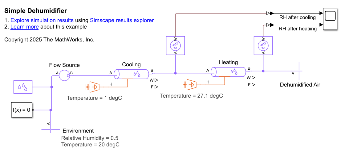
Model a Simple Dehumidifier
Model a simple dehumidifier. You examine a model of a dehumidifier, then observe how changing the entrained water droplet and condensation settings affect the model behavior.
Ports
Output
Conserving
Parameters
References
[1] White, F. M., Fluid Mechanics. 7th Ed, Section 6.8. McGraw-Hill, 2011.
[2] Cengel, Y. A., Heat and Mass Transfer – A Practical Approach. 3rd Ed, Section 8.5. McGraw-Hill, 2007.
[3] Mitchell, John W., and James E. Braun. Principles of Heating, Ventilation, and Air Conditioning in Buildings. Wiley, 2013.