Create DHT11 Sensor Block to Measure Relative Humidity and Temperature Using IO Device Builder App
This example shows how to use the IO Device Builder app to create DHT11 sensor for measuring relative humidity and temperature. In this example, the DHT11 sensor communicates with a Microcontroller through a single-wire interface. The communication protocol is a proprietary one-wire protocol that uses a timing-based communication scheme. It detects water vapor by measuring the electrical resistance between two electrodes, and it measures temperature with a surface-mounted NTC temperature sensor (Thermistor) built into the unit.
Note:
By default, communication libraries such as SPI, I2C, and Servo are included. For information on adding other libraries, see Working with Arduino Libraries in IO Device Builder.
The IO Device Builder app supports only Monitor & Tune (External mode) and Build, Deploy & Start options. Connected IO is not supported.
Prerequisites
Download and extract the following zip files from GitHub®.
DHT-sensor-library drivers for the sensor
Dependent files Adafruit Unified Sensor
Circuit Connections
To run this example, make these circuit connections.
For 5.0V LOGIC boards: Connect 5V on the Arduino® to VIN on the DHT11
For 3.3V LOGIC boards: Connect 3.3V on the Arduino to VIN on the DHT11.
Connect GND on the Arduino to GND on the DHT11.
Connect the signal pin on the DHT11 to the digital pin 10 on the Arduino.
Open the IO Device Builder App
To open the IO Device Builder app, perform these steps.
Start MATLAB® and then open / create a Simulink® model.
Go to Modeling > Model Settings to open the Configuration Parameters dialog box.
Open the Hardware Implementation pane, and select a Arduino board.
On the Hardware tab of the Simulink toolstrip, in Prepare section, under Design, choose IO Device Builder.

Select Working Directory and Add Third-Party Source Files
Once the Source files location page loads, select the working directory and add third-party source files.

On the Source files location page:
Click Select and select the working directory. In the working directory, the generated System object™, along with the corresponding cpp and h files, and the model are located.
Click Add folder and add the DHT-sensor-library and Adafruit_Sensor-master folders you downloaded. Only the files present directly within the selected folder are included, and any files present within subfolders are excluded.
Click Next to continue.
Select Source Files

On the Source files page, select the required source files and then click Next to continue.
Specify Block Parameters

On the Block parameters page:
Specify the block name and add block description.
Add parameter
dataDelaywith Data typeuint32and Dimension[1,1].Click Next to continue.
Select Outputs for the Block

On the Outputs page:
Add
HumidityandTemperatureas Outputs with Data type assingleand Dimension[1,1].Click Next to continue.
Select Inputs for the Block

On the Inputs page:
Remove inputs for the block, if any already added.
Click Next to continue.
Preview Block

On the Block image page, view the preview of the block with the inputs and outputs you added. Click Next to continue.
Generate System Object Files

The app displays the location of the System object file on the Generate page. Choose the Select to generate a C++ driver option, if you want to generate a C++ file.
Click Generate to generate the System object files.
Next Steps

On the Next Steps page, the files generated are shown and the next steps to be performed are displayed. The generate files are created in a directory. This directory also includes a Dependencies folder that contains selected third-party source files. Simply copy these files and the folder to your desired location and integrate them into your Simulink project.
Click Finish on this page to complete the process. The generated .cpp file opens automatically.
Perform these steps.
1. Modify the generated .cpp file to include the necessary headers and setup functions by referring to the driver file as required.
#include "C:\user\dht11\dht11Sensor.h"  //App generated header. Do not modify.
#include "Adafruit_Sensor.h"
#include "DHT.h"
#include "DHT_U.h"
#include "Arduino.h"

#define DHTPIN 10
#define DHTTYPE    DHT11
DHT_Unified dht(DHTPIN, DHTTYPE);
uint32_t delayMS;
void setupFunctiondht11Sensor(uint32_T * dataDelay,int size_vector__1){
    dht.begin();
    delayMS = dataDelay;
}

void stepFunctiondht11Sensor(float * Humidity,int size_vector_1,float * Temperature,int size_vector_2){
    delay(delayMS);
    sensors_event_t event;
    dht.temperature().getEvent(&event);
    if (isnan(event.temperature)) {
    }
    else {
        *Temperature=event.temperature;

    }
    dht.humidity().getEvent(&event);
    if (isnan(event.relative_humidity)) {
    }
    else {
        *Humidity=event.relative_humidity;
    }
}
2. Assign the output to the selected output port.
3. Add the #include "Arduino.h" header and other required headers for the driver, as mentioned in the example with the absolute address.
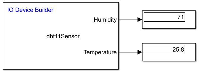
4. In the already opened Simulink model, add a Display to the output ports.
5. In the Simulink model, navigate to Modeling > Model Settings and in the Configuration Parameters dialog box, click Hardware Implementation and then select an Arduino board.
A sample Simulink model is shown here.