Code Generation Simulink Template for Parrot Minidrone
After you have completed Setup and Configuration, use the Code Generation Simulink® template to create a model to be deployed on your Parrot® minidrone hardware. This template is designed to spin the four motors on the drone cyclically for 2 seconds each. You can update this template to add your own logic to start the drone.
Open the Code Generation Template
At the MATLAB® command prompt, type
simulink.On the Simulink Start Page, navigate to Simulink Support Package for Parrot Minidrones, and select Code Generation Template.
A Simulink model opens. This model is configured for code generation and contains two inports, two outports, and a subsystem block. For more information, see Inports in Code Generation Template and Outports and Signals in Code Generation Template.
Note
The Code Generation Template is available only if you have installed Simulink Support Package for Parrot Minidrones. For more information, see Setup and Configuration.

Inports in Code Generation Template
The Code Generation Template model contains two inport blocks,
AC cmd and Sensors:
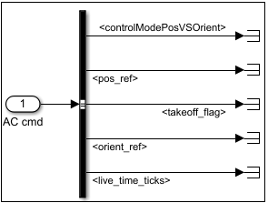
AC cmd– This inport is connected to a Bus Selector block that provides five output signals:
<controlModePosVSOrient>– Checks for the presence of pitch and roll values in theorient_refsignal. This signal is set totrueif both pitch and roll values are zero.The
<controlModePosVSOrient>signal can be used to determine if the controller logic that drives the drone uses orientation or position control. If one or both of the pitch value or roll value is present, the drone will fly based on those orientation values only, and it will ignore any reference to the desired position of the drone specified using the<pos_ref>signal.<pos_ref>– An array representing x-, y-, and z-axes values (in meters) of the desired position of the drone.<takeoff_flag>– A flag that is set to true for 1 second. After you execute the start command, there is a calibration period for 2 seconds, after which the<takeoff_flag>is set to true for 1 second. This flag is disabled after that 1-second period. This flag can be used to include any additional logic that needs to be considered when the motors on the drone start (for example, to separate the logic required for take-off and hovering).<orient_ref>– An array representing the yaw, pitch, and roll values (in radians per second) that determine the orientation of the drone.<live_time_ticks>– This signal represents a continuous counter that is incremented at the rate of 5 ms (200 Hz frequency). This counter is present in the control code that is running in the drone at every 5 ms. In other words, the<live_time_ticks>value is incremented by 200 each second.
Note
In the Code Generation Template, the signals from the
AC cmdblock are terminated. However, you can connect the signals when you design a model based on the template.Sensors– This inport is connected to a Bus Selector that provides output signals that are derived from the different sensors on the drone. TheSensorsinport is further divided intoVisionSensors,HALSensors, andSensorCalibration.
VisionSensorsconnects to a Bus Selector block that provides three output signals:
<opticalFlow_data>– Obtains the values of horizontal displacement of the drone based on optical flow data. This signal can be used to estimate the speed of the drone.<posVIS_data>– Data from the image processing thread that is running inside the drone, which in turn is based on the data from the camera on the drone.Currently, the data from the image processing thread is not passed to the
<posVIS_data>signal, so this signal returns zero values.<usePOSVIS_flag>– A flag that determines whether the<posVIS_data>signal is to be used in the controller logic or not.Currently, the
<usePOSVIS_flag>is always set to false.
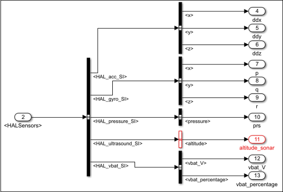
HALSensorsconnects to a Bus Selector block that derives values from the Hardware Abstraction Layer (HAL) of the drone. The signal values are obtained from the accelerometer, gyroscope, pressure sensor, ultrasonic sensor, and battery:
<HAL_acc_SI>– An array representing the acceleration of the drone (in ㎨) along x-, y-, and z-axes.<HAL_gyro_SI>– An array representing the angular velocity of the drone (in radians per second) along x-, y-, and z-axes.<HAL_pressure_SI>– Atmospheric pressure (in pascals) measured by the drone.<HAL_ultrasound_SI>– Altitude of the drone (in meters) measured using sonar.<HAL_vbat_SI>– An array representing the voltage of the battery (in volts) and the percentage of charge remaining.
SensorCalibrationprovides calibrated values of the different sensor values. The calibration is performed over 400 cycles (2 seconds), and you can obtain eight values that include:calibrated x, y, and z values of acceleration
calibrated x, y, and z values of angular velocity
calibrated atmospheric pressure
calibrated altitude
Outports and Signals in Code Generation Template
The outports in the Code Generation template are:
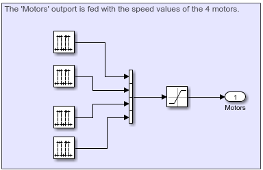
Motors– This outport is used to send signals to start the four motors on the drone.In the Code Generation template, four Pulse Generator blocks are used to send signals to the four motors. The amplitude values in these blocks are set to 400, which spins the motors at the corresponding speed. A phase shift is also provided in the Pulse Generator so that the four motors spin cyclically for 2 seconds each.
When you design your own controller logic, the signals to the motors can be derived from the output of controller logic. (Use 1-by-4 vector as the input to the
Motorsoutport.)
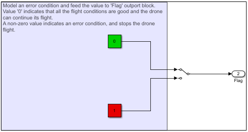
Flag– This outport is used to set error conditions that can be used to stop the flight of the drone (stop the motors). A value of 0 indicates that there are no errors, and any nonzero value indicates an error. You can model multiple error conditions in the controller logic that correspond to multiple nonzero values that can be fed as input to this flag.
For details about setting the hardware and deploying the model, see Setting Up the Hardware and Deploying the Model.
See Also
Setting Up the Hardware and Deploying the Model | Flight Simulation Simulink Template for Parrot Minidrone