Propagate Variant Conditions to Define Variant Regions Outside Variant Subsystems
Simulink® propagates variant conditions from Variant Subsystem blocks to their connecting blocks. The propagation of variant conditions enables Simulink to determine which components of the model remain active during simulation. Simulink then deactivates the model components associated with the inactive choices and highlights the active connections. By default, variant conditions do not propagate outside the Variant Subsystem block. To allow variant conditions to propagate to the connecting blocks, select the Propagate conditions outside of variant subsystem parameter on the Variant Subsystem block. For more information about the Variant Subsystem block, see Variant Subsystem, Variant Model, Variant Assembly Subsystem.
Tip
Variant condition annotations on model components help you visualize the propagated conditions. To view the annotations, on the Debug tab, select Information Overlays > Variant Legend. If Variant Legend is not available, on the Debug tab, select Information Overlays > Variant Conditions. For more information, see Visualize Propagated Variant Conditions in Variant Conditions Legend.

Factors That Affect Propagation of Variant Conditions Outside of Variant Subsystem Blocks
The propagation of variant conditions outside of a Variant Subsystem block depends on the variant activation time of the block and the interface of the underlying variant choices. The Variant activation time parameter determines if Simulink must analyze only the active choice or both active and inactive choices of the block when simulating the model. If the interface of the analyzed variant choices matches the interface of the Variant Subsystem block, the variant conditions do not propagate outside the Variant Subsystem block. In other words, if the analyzed variant choices use all the input and the output signals of the Variant Subsystem block, the variant conditions do not propagate outside of the block. The variant conditions propagate outside of the Variant Subsystem block only if the interfaces do not match.
Adaptive Interface for Variant Subsystems
This example shows how propagating variant conditions outside a Variant Subsystem block enables the block to adapt its interface according to the states of the underlying blocks for different activation times. The example also explains the code that is generated for different activation times. For information on factors that affect the propagation, see Factors That Affect Propagation of Variant Conditions Outside of Variant Subsystem Blocks.
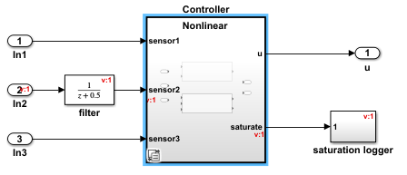
Consider the slexVariantSubsystemsAdaptiveInterface model containing a Variant Subsystem block named Controller with two variant choices, Linear and Nonlinear. The Linear controller is active when V == 1, and the Nonlinear controller is active when V == 2. V is a variant control variable and is defined in the PreLoadFcn callback of the model.
To change the value of the variant control variable, in the MATLAB™ Command Window, type V = 1 or V = 2.

Double-click the Controller block to view its contents. The Linear and Nonlinear controller blocks do not have the same interface. The inports sensor1 and sensor3 are used in Linear controller and Nonlinear controller blocks, but sensor2 is used only in Linear controller block. Hence, the sensor2 block is active only when the Linear controller is active and is not executed when the Nonlinear controller is active. To make the model components outside the Controller block aware of the active or inactive state of blocks within the Controller block, the block variant conditions must propagate outside the boundaries of the block. To propagate the variant conditions outside of the Controller block, select Propagate conditions outside of variant subsystem in the Block Parameters dialog box of the block. By default, this parameter is set to off.
To simulate the model and generate code for Linear and Nonlinear controllers, perform these steps:
1. In the Block Parameters dialog box of the Controller block, set an activation time in the Variant activation time parameter.
2. To activate the Linear controller and its connected blocks, change the value of V to 1.
3. Simulate the model and observe the propagated conditions as described in Propagation with Different Activation Times.
4. Generate code from the model by using Embedded Coder®. For information on how to generate the code, see Generate Code Using Embedded Coder (Embedded Coder). Observe the results as described in Propagation with Different Activation Times.
Note
In the model, the saturate port is an unconnected output port and so it is not included in the generated code for any variant activation times.
5. Similarly, to activate the Nonlinear controller and its connected blocks, change the value of V to 2 and simulate the model. Generate code from the model and observe the results.
Propagation with Different Activation Times
This section explains the simulation results and the code generated for
Linear and Nonlinear controllers with
different activation times.
Propagate Variant Conditions for update diagram Activation Time
This table compares the propagation of variant conditions and the generated
code for the Linear and Nonlinear
controller choices for update diagram activation
time.
When V == 1 and Linear
controller is active | When V == 2 and
Nonlinear controller is active |
|---|---|
|
|


Note
When propagating the variant conditions outside of a Variant
Subsystem with update diagram
activation time:
If you set Allow zero active variant controls to
on, Simulink propagates the variant conditions to all the blocks (including the unconditional or alwaystrueblocks) of the variant region. Propagating conditions to all the blocks of the variant region enables Simulink to completely remove the variant region from the model when none of the variant choices are active.The code that you generate is the same regardless of the setting of Allow zero active variant controls.
Propagate Variant Conditions for update diagram analyze all choices Activation Time
This table compares the propagation of variant conditions for the
Linear and Nonlinear controller
choices with update diagram analyze all choices
activation time. The generated code is the same as update
diagram.
When V == 1 and Linear
controller is active | When V == 2 and
Nonlinear controller is active |
|---|---|
|
|

Note
When propagating variant conditions outside of a Variant
Subsystem with update diagram analyze all
choices activation time:
If you set Allow zero active variant controls to
on, Simulink propagates the variant conditions to the all the blocks (including the alwaystrueor unconditional blocks) of the variant region. Propagating conditions to all the blocks of the variant region enables Simulink to completely remove the variant region from the model when none of the variant choices are active.The code that you generate is the same regardless of the setting of Allow zero active variant controls.
Propagate Variant Conditions for code compile Activation Time
The propagation of variant conditions for Linear and
Nonlinear controller choices with code
compile activation time is the same as propagation with
update diagram analyze all choices. The code that
is generated for the Linear and Nonlinear
controllers is as shown.
The code contains Linear and Nonlinear
choices enclosed in necessary preprocessor conditionals #if
and #elif.
//slexVariantSubsystemsAdaptiveInterface.c
/* Model step function */
void step(void)
{
#if V == 1
// Logic for Linear choice
#elif V == 2
// Logic for Nonlinear choice
}
/* Model initialize function */
void initialize(void)
{
/* (no initialization code required) */
}
The port sensor2, which is not used by all the variant
choices, is also enclosed in preprocessor conditional
#if.
//slexVariantSubsystemsAdaptiveInterface.h
External inputs (root inport signals with default storage)*/
typedef struct {
real_T In1; /* '<Root>/In1' */
#if V == 2
real_T In2; /* '<Root>/In2' */
#define EXTERNALINPUTS_VARIANT_EXISTS
#endif
real_T In3; /* '<Root>/In3' */
} ExternalInputs;
// External outputs (root outports fed by
// signals with default storage)
typedef struct {
real_T u;
} ExternalOutputs;Note
When propagating variant conditions outside of a Variant
Subsystem block with the code compile
activation time, if you set Allow zero active variant
controls to on, Simulink propagates the variant conditions to all the blocks (including
the always true or unconditional blocks) of the variant
region. In the generated code, the blocks of the variant region are enclosed
in an additional variant condition that is the logical OR of conditions from
the variant choices. This enables Simulink to remove the variant regions completely from the model when
none of the variant choices are active. In this example, the always
true blocks In1 and
In3, and the variant choices
Linear and Nonlinear are enclosed
in the logical OR of variant conditions, V == 1 || V ==
2. When V == 1 and V == 2
each evaluate to false, Simulink skips the compilation of these blocks thus removing the
variant regions completely.
Propagate Variant Conditions for startup Activation Time
The propagation of variant conditions for the Linear and
Nonlinear controller choices with
startup activation time is the same as
propagation with update diagram analyze all choices
activation time.
The code that is generated for the Linear and
Nonlinear controllers is as shown.
The code contains Linear and Nonlinear
choices enclosed in regular if and else if
conditions.
//slexVariantSubsystemsAdaptiveInterface.c
/* Model step function */
void step(void)
{
if (V == 1)
// Logic for Linear choice
else if (V == 2)
// Logic for Nonlinear choice
}
/* Model initialize function */
void initialize(void)
{
startupVariantChecker();
}
static void startupVariantChecker(void)
{
/* startup variant condition checks */
utAssert((rtP.V == 1.0) + (rtP.V == 2.0) == 1);
}The ports are unconditional.
//slexVariantSubsystemsAdaptiveInterface.h
/* External inputs (root inport signals with default storage) */
typedef struct {
real_T In1; /* '<Root>/In1' */
real_T In2; /* '<Root>/In2' */
real_T In3; /* '<Root>/In3' */
} ExternalInputs;
// External outputs (root outports fed by signals
// with default storage) */
typedef struct {
real_T u; /* '<Root>/u' */
} ExternalOutputs;
Note
When propagating variant conditions outside of a Variant
Subsystem block with the startup
activation time, if you set Allow zero active variant
controls to on, Simulink propagates the variant conditions to all the blocks (including
the always true or unconditional blocks) of the variant
region. In the generated code, the blocks of the variant region are enclosed
in an additional variant condition that is the logical OR of conditions from
the variant choices. This enables Simulink to remove the variant regions completely from the model when
none of the variant choices are active. In this example, the always
true blocks In1 and
In3, and the variant choices
Linear and Nonlinear are enclosed
in the logical OR of variant conditions, V == 1 || V ==
2. When V == 1 and V == 2
each evaluate to false, Simulink skips the compilation of these blocks thus removing the
variant regions completely.
Propagation Without Inport and Outport Blocks
Consider this model that has a Variant Subsystem block
Controller with two variant choices. The block does not have
any inports or outports. The first variant choice has the condition V ==
1, while the second variant choice has the condition W ==
1.
In this model, the variant conditions from the Controller block
without inports or outports propagate outside the subsystem in the same way as a
Variant Subsystem block with inports and outports. The activation
times and the allowance of zero active variant controls also have the same impact on
condition propagation.
During simulation with these settings, the variant conditions propagate as follows:
When you set the Propagate conditions outside of variant subsystem parameter to
off, no variant conditions apply to theControllerblock. This is because the interface of theControllerblock remain the same regardless of the active choice due to its shared interface with the choice blocks. When you set the Propagate conditions outside of variant subsystem parameter toon, the variant condition of the active choice applies to theControllerblock so that the variant condition propagates to the connected blocks, if any. In this example, no blocks that connected.With the Allow zero active variant controls parameter set to
on, the variant conditions propagate to all blocks within the variant region, including unconditional blocks such as theControllerblock in this example, enabling the complete elimination of the variant region when none of the choices are active.Setting the Variant activation time parameter to
code compileorstartup, adds an additional variant condition in the generated code that encloses the blocks within the variant region. In this example, the variant condition is a logical OR of the variant conditionsV == 1andW == 1.

Limitations
Propagated variant conditions from variant subsystems can be set on Simscape™ or Stateflow® blocks only for the update diagram variant
activation time.
Related Topics
You can also select a web site from the following list:
Americas
- América Latina (Español)
- Canada (English)
- United States (English)
Europe
- Belgium (English)
- Denmark (English)
- Deutschland (Deutsch)
- España (Español)
- Finland (English)
- France (Français)
- Ireland (English)
- Italia (Italiano)
- Luxembourg (English)
- Netherlands (English)
- Norway (English)
- Österreich (Deutsch)
- Portugal (English)
- Sweden (English)
- Switzerland
- United Kingdom (English)