Analyze Model and Interpret Results
The Simulink® Design Verifier™ analysis workflow streamline the verification process and guides you from model preparation through to results interpretation. By using Simulink Design Verifier, you can enhance model reliability, reduce development time, and achieve higher confidence in your system designs.
The Simulink Design Verifier workflow involves preparing your Simulink model or requirements for the analysis as an input.

Next you analyze Simulink models with Simulink Design Verifier using analysis modes to:
Generate test cases that achieve model coverage.
Detect design errors that can occur at a run time.
Prove properties and identify property violations.
Once the analysis is complete, you review the results to identify any design errors or validate model properties. The workflow concludes with reviewing the analysis results or export the results to create test harness.
The workflow in this tutorial focuses on Simulink Design Verifier analysis steps.
Check Model Compatibility
Before Simulink Design Verifier analyzes a model, the software checks whether the model is compatible for analysis. For more information on model compatibility, see Check Model Compatibility for Analysis. The software runs a compatibility check on your model, and then creates a model representation. The model representation includes the model artifacts that you can use during analysis. The compatibility check tells you if your model is fully compatible, partially compatible, or not compatible.
Simulink supports a broad range of software capabilities in your models but there are some capabilities that Simulink Design Verifier does not support. For more information, see Unsupported Simulink Blocks in Analysis and Limitations of Simulink Design Verifier for Simulink Software Features.
Apply Block Replacement Rules
If you want to work around the compatibility limitations in your model or customize model elements for analysis, you can use the Simulink Design Verifier block replacement rules. For more information, see Perform Analysis Using Block Replacement.
If you want to generate additional values for parameters in your model during analysis, use Simulink Design Verifier parameter configurations. See Use Parameter Configuration in Analysis for more information.
Set Simulink Design Verifier Options
You can set the Simulink
Design Verifier analysis options in the
Configuration Parameters dialog box. Alternatively, you can use the sldvoptions function to specify the Simulink
Design Verifier options at the command line. For more information, see Configure Analysis Options for Model.
Perform Analysis on Model
You can analyze your model for:
Design Error Detection: Detect design errors that can occur at run time. For more information, see Analyze Models for Design Errors.
Test Case Generation: Generate test cases that achieve model coverage. For more information, see Workflow for Test Generation.
Property Proving Analysis: Prove properties and identify property violations. For more information, see Workflow for Proving Model Properties.
If you plan to generate test cases or prove properties in your model, first run design error detection for integer overflow and division by zero. Refer to these topics for more information:
Generate Analysis Results
Once Simulink Design Verifier finishes analyzing the model, it displays the analysis highlights and the results options in the Results Summary window. For more information, see Perform Analysis on a Model.
Interpret Analysis Results
You can the review analysis results and generate analysis reports in the HTML, DOCX, or PDF format. For more information, see Review Analysis Results.
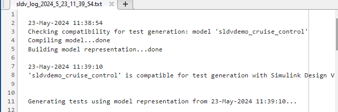
Every time you analyze a model, Simulink Design Verifier creates a log file.
To view the log file, click View Log in the Simulink Design Verifier log window.
The log file generates in .txt format and characters that do not originate from the current locale are corrupted in the log file.
The log file contains a list of the analysis results for each object in the model. The content of the log file corresponds to the analysis results displayed in the log window during the analysis.
Simulink Design Verifier Block Library
The Simulink Design Verifier block library has three categories of blocks:
Objectives and Constraints — Blocks that define custom objectives and constraints
Temporal Operators — Blocks that define temporal properties on Boolean signals
Verification Utilities — Miscellaneous verification utilities
To open the Simulink
Design Verifier block library, at the MATLAB® command prompt, type sldvlib.
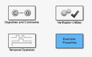
The block library also has a sublibrary, Example Properties, that includes examples of how to specify common properties in your model. You can easily adapt these examples for use in your models.
See Also
Analyze Models for Design Errors | Perform Analysis Using Block Replacement