Increase Coverage by Generating Test Inputs
Using Simulink® Design Verifier™, you can generate test inputs that replicate design errors, achieve test objectives, or meet coverage criteria. Simulink Test™ can create test cases that use test inputs and expected outputs from Simulink Design Verifier.
Overall Workflow
Test case generation follows this workflow.
Choose an existing Simulink Design Verifier results file, or generate new results by analyzing your model.
If you use an existing results file, you can load results by either:
Using the Simulink Test command
sltest.import.sldvData.Using Simulink Design Verifier menu items. In the model, on the Apps tab, under Model Verification, Validation, and Test, click Design Verifier. On the Tests tab, click Simulink Test Manager. In the Review Results section, click Load Earlier Results. Select the MAT file with the analysis results.
If you run a model analysis, the Simulink Design Verifier Results Summary window appears after the analysis completes.
In the results summary window, click Export test cases to Simulink Test. Test cases and iterations for Requirements Table blocks are linked automatically to the corresponding requirements.
Enter the name of an existing or new test harness.
Select a test harness source for the generated test inputs. You can select
Inport: The inputs are contained in the Simulink Design Verifier data file and mapped to Inport blocks in the test harness. The mapping is shown in the Inputs section of the test case. Using theInportoption allows you to map other inputs to the test harness Inport blocks, which can be useful for running multiple test cases or iterations using the same test harness. Both MAT and Excel® files are supported when the source isInport.Signal Editor: The inputs are in scenarios in a Signal Editor block inside the test harness. The Signal Editor block supports MAT files that contain these inputs. You can edit these scenarios in the Signal Editor. See Use Scenarios and Insert Signals in Signal Editor.
Select a new or existing test file, and enter names for the test file and test case.
Click OK to export the test cases to Simulink Test. The test files and test cases are updated in the Test Manager. Simulink Design Verifier saves a MAT or Excel data file that also includes parameter settings. You can view or override these settings in the Parameter Overrides section of the Test Manager.
Note
Another way to import test cases from Simulink Design Verifier is with the Create Test for Component wizard. For information, see Generate Tests and Test Harnesses for a Model or Components.
Generate Test Cases Using Simulink Design Verifier
This example shows how to generate test cases for a controller subsystem using Simulink Design Verifier, and export the test cases to a test file in Simulink Test. The example requires a Simulink Design Verifier license.
The model used in this example is a closed-loop heat pump system. The controller inputs are the measured room temperature and the set temperature. The controller outputs a bus of three signals that control the fan, heat pump, and direction of the heat pump (heat or cool). The model contains a harness that tests the heating and cooling scenarios.
Open the Model
sltestTestCaseFromDVExample
Generate Tests and Export to Simulink Test
1. Right-click the Controller block and select Design Verifier > Generate Tests for Subsystem. Simulink Design Verifier generates the tests for the component.
2. In the results summary window, click Export test cases to Simulink Test.
3. In the Export Design Verifier Test Cases dialog box, enter:
Test Harness:
TestHarness1Harness Source:
Signal EditorSelect Use a new test file
Test File:
TestFile_GeneratedTests.mldatxTest Case:
<Create a new test case>
4. Click OK.
A new test file is created in the working folder, and a test harness, owned by the Controller subsystem, is added to the main model. Click the harness badge to preview the new test harness.
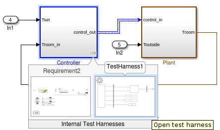
5. Click the TestHarness1 thumbnail to open the harness. Then double-click the Harness Inputs Signal Editor block source.
6. In the Block Parameters: Harness Inputs dialog box, click Launch Signal Editor ![]() .
.
7. To see the test inputs in the Signal Editor, expand a test case and select the inputs.

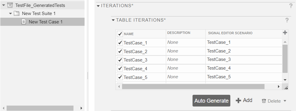
8. In the Test Manager, the new test case displays the system under test, and the test harness containing the generated inputs in the Signal Editor source. Expand the Iterations section to see the iterations corresponding to the signal scenarios.