Belt-Cable Spool
Source and sink of cord in a pulley system

Libraries:
Simscape /
Multibody /
Belts and Cables
Description
The Belt-Cable Spool block represents a cylindrical drum on which to wind (and from which to unwind) the cord of a pulley system. The spool marks an end to the cord and the point at which a motor or other power source often pulls on a load. A Belt-Cable End block generally marks the second tip of the cord, to which the load itself is commonly attached. Depending on whether it is winding or unwinding, the spool can behave as an infinite source of cord or as an infinite sink of the same.

The spool serves as an interface between the belt-cable domain specific to pulley systems and the frame domain general to all other multibody components. The belt-cable port (A) identifies the tip of the cord to be wound on the spool and the relative placement of that tip within a pulley system. A frame port (R) identifies the reference frame of the spool and its placement in the broader multibody model.
The degrees of freedom of the spool are a function of the joint by which the spool connects to other components. It is common for a revolute joint to provide those degrees of freedom; they reduce in this case to rotation about a single axis (that of the spool). Actuation inputs, specified directly through the joint by means of torque or motion signals, serve to drive the spool and to wind (or unwind) the cord.
The cord enters and exits the drum in tangency with the drum circumference. Consistent with the right-hand rule, the winding is in a counterclockwise direction about the rotation axis of the drum. This axis is by definition the z-axis of the local reference frame (R). To reverse the direction of the winding, you must flip the local reference frame so that the z-axis points in the opposite direction—for example, by the application of a frame rotation through a Rigid Transform block.
The surface of the spool (smooth or grooved) is not considered in the model. In addition, the cord is assumed to wrap around the spool in a circle that is of constant radius (that of the pitch circle) and coplanar with the transverse cross section of the winch. Changes in spool radius due to winding are ignored.
By default, the cord can enter and exit a spool at an angle to its center plane (θ in the figure). This angle can vary during simulation—for example, due to translation of the spool on a prismatic joint. While the contact point is always in the center plane of the spool, the spool can move when mounted on a joint. The cord can also be constrained to enter and exit the spool in its center plane. Whether this constraint is enforced depends on the settings of the Belt-Cable Properties block.

The inertia of the spool and of the cord wound on it are also ignored. To capture the inertia of a spool of fixed mass, use the Cylindrical Solid or Inertia block. Consider the Cylindrical Solid block if solid geometry is important in the model. To capture the variable mass properties of a cord as it winds on, and unwinds from, the spool, use a block from the Variable Solids library—for example Variable Cylindrical Solid or General Variable Mass.
Examples
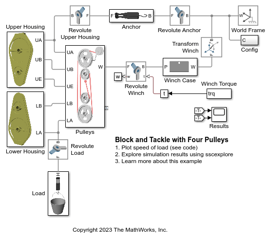
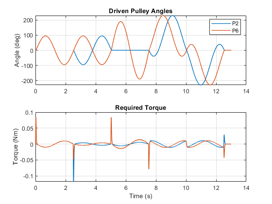
Block and Tackle with Four Pulleys
Models a block and tackle with four pulleys. Torque is applied to a winch which acts through the pulley mechanism to lift a load. Blocks from the Simscape™ Multibody™ Belts and Cables library are used to model the block and tackle.
Cable-Driven Cross Slide Table
Models an XY cross positioning table that uses a cable-driven mechanism. A single cable wraps around seven different pulleys and converts the rotational angle of the two input pulleys to the x-y position of the table.

Cable Robot
Models a cable robot. The robot comprises 8 independent belt-cable circuits which control the 6 degrees-of-freedom of the mover. A ball is dropped from a fixed height down the center axis of the mechanism. The mover initially starts directly below the ball and the contact is modeled between the mover and the ball such that the ball bounces elastically when striking the mover. The objective of the mover is to perform increasingly complex maneuvers between successive bounces of the ball. The mover is motion actuated from which the necessary cable, pulley, and motor spool kinematics are computed.
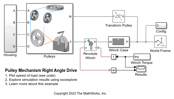
Pulley Mechanism Right Angle Drive
Models a pulley mechanism that takes a torque applied to a winch and transmits it to a pulley rotated at 90 degrees to that winch. This example uses blocks from the Simscape Multibody Belts and Cables library to model a pulley mechanism that is not all in a single plane.
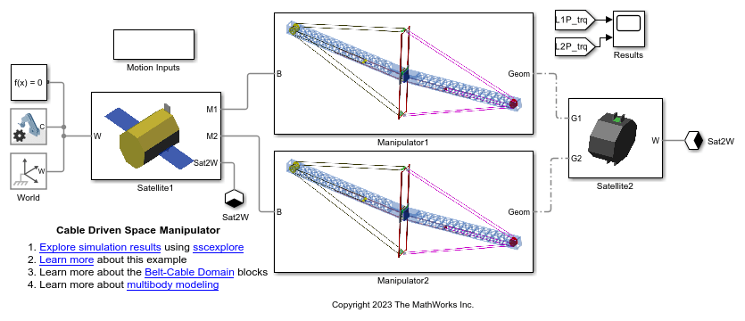
Cable Driven Space Manipulator
Models a cable driven space manipulator. The manipulator comprises of 2 links connected via a system of revolute joints. Each link consists of belt-cable circuits which drive the movements of the manipulator. It also consists of a spring-damper system which provides different stiffness requirements. A space application is shown in this example where the objective of the manipulators is to capture a small satellite. The manipulators start from folded states and then perform necessary maneuvers to extend and reach the desired position. The pulleys are motion actuated from which necessary belt-cable kinematics are computed.

Tower Crane with Trolley and Hoist
Models a tower crane with a trolley and a hoist. The hoist can raise and lower a load, and the trolley moves the load towards and away from the tower. Blocks from the belts and cables library are used to model the pulleys that control lifting the load and moving the trolley.

Elevator
Models an elevator system in Simscape™ Multibody™. The system is comprised of belt-cable pulley circuits which control the movement of the elevator and the door mechanism. The cable is approximated to be extensible by using high stiffness springs between the belt cable ends and the elevator. The motor pulley is motion actuated based on the necessary elevator kinematics computed from the Floor Number inputs. Effects of people entering and leaving the elevator are modeled using general variable mass blocks.

Forklift
Models a forklift which uses the hydraulic and pulley mechanisms to perform the lift action. The tilting of masts is also controlled by hydraulic cylinders. The forklift comprises of 3 masts, namely main mast, top mast and fork mast. The main mast is connected to the chassis by revolute joints and its tilting is governed by the hydraulic tilt cylinders. The top mast slides over the main mast and its motion is governed by the hydraulic lift cylinders. The fork mast slides on the top mast and hangs through belt-cable circuits which drives the movement of the fork mast. A common warehouse application is shown in this example where the objective of the forklift is to grab a box, pass over a bump and place the box in the racks. Spatial Contact Force blocks are used at all contact locations to model the contact between the bodies. The contact between the ground surface and the wheels are modeled using infinite plane block and the contact between the forks and the box are modeled using the point blocks.
Ports
Frame
Belt-Cable
Parameters
Extended Capabilities
Version History
Introduced in R2018a