Main Content

Measurements and States Analyzer

Compute initial and steady-state values of voltages and currents of model

Since R2021a

Description

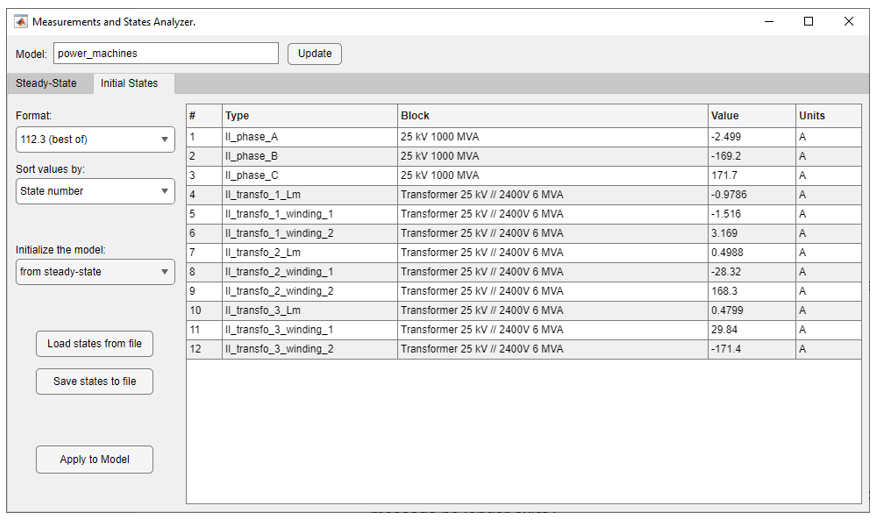
The Measurements and States Analyzer app computes the initial states and steady-state values of the inductor currents and capacitor voltages (electrical state variables), and the steady-state voltages and currents of measurement blocks, sources, and nonlinear blocks in a model. The app uses the power_initstates function to compute the initial state values, and the power_steadystate function to compute the steady-state values.

Measurements and States Analyzer app

Open the Measurements and States Analyzer App

  • powergui Block Parameters dialog box: On the Tools tab, click Measurements and States Analyzer.

  • MATLAB® command prompt: Enter powerStates or powerStates('sys'), where sys is the name of the model.

Parameters

expand all

Enter the name of the model for which you want to compute the initial states and steady-state values.

Recompute and display the steady-state measurements.

Steady State

Format in which you want your measurements displayed. 4.503e+004 (floating point) displays values in mantissa-exponent form with five significant figures. 112.3 (best of) displays values with four significant figures and uses mantissa-exponent form only for numbers larger than 9999. 2590571.12 displays in plain numbers with two figures to the right of the decimal point.

Set to Peak values to display the peak values of the selected values. Set to RMS values to display the root-mean-square (RMS) values of the selected values.

Choose the frequency, in hertz (Hz), in which you want to display the voltage and current phasors. The Frequency parameter lists all the different frequencies of the electrical sources of the model.

Select to display the steady-state values of the inductor currents and capacitor voltages.

Select to display the steady-state values of the measurement blocks in the circuit.

Select to display the steady-state voltage and currents of the electrical sources of the circuit.

Select to display the steady-state voltage and currents of the nonlinear blocks of the circuit.

Initial States

Format in which you want your measurements displayed. 4.503e+004 (floating point) displays values in mantissa-exponent form with five significant figures. 112.3 (best of) displays values with four significant figures and uses mantissa-exponent form only for numbers larger than 9999. 2590571.12 displays in plain numbers with two figures to the right of the decimal point.

State number displays the value according to the states ordering in the state-space model. Type displays the values grouped by capacitors and inductors.

Select from steady-state to force all initial electrical state values to steady-state values. When this option is selected, the Value column of the right pane is disabled because all states are forced to steady-state values. Select from zero to force all initial electrical state values to zero. When this option is selected, the Value column of the right pane is disabled because all states are forced to zero. Select from user settings to enable the Value column of the right pane and edit the initial state values to custom values.

Load the initial state settings of the model from a file.

Save the initial state settings of the model in a file.

Apply the current parameter settings to the model.

Version History

Introduced in R2021a