Analysis of Solar Photovoltaic System Shading
This example shows how to implement shading effects in a solar photovoltaics (PV) plant or module. The solar plant block is created using Simscape™ language. Shading in a solar plant or module occurs when solar irradiance is not uniform across all solar PV modules or cells. You can use this example to study the effects of shading and PV cell junction temperature in a large interconnected solar plant or a single PV module. To improve the maximum power and to protect the solar panel from overheating, the Solar Plant block comprises bypass and blocking diodes. To define the shading, set the values of the Irradiance and Temperature parameters.
Model Overview

Solar Plant Block Overview
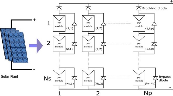
This figure shows a Solar Plant block. The Solar Plant block comprises Np parallel-connected strings. Each string comprises Ns series-connected solar PV modules.

Photovoltaic Solar PV Module Overview
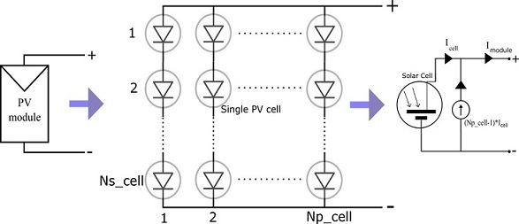
The Solar Plant block comprises Ns*Np PV modules. Each solar PV module consists of Np_cell parallel-connected strings and each string comprises Ns_cell series-connected solar cells. A Solar Cell block from the Simscape™ Electrical™ library models the solar cell strings. To specify the size of the PV module, define the number of cells, Ns_cell and Np_cell, in the modules. To replicate a commercially available solar panel, the solar PV module parameters are directly obtained from a solar panel manufacturer datasheet. For more information about manufacturer datasheet-based parameterization, see the Simscape Electrical 'SolarPanelValidation' example.

Protection Diode
The Solar Plant block comprises both bypass and blocking diodes. A Diode block from the Simscape foundation library models the protection diodes. To bypass the solar PV module in a string that does not have enough irradiance to support the solar PV string current, bypass diodes are connected across PV modules. The blocking diodes isolates the solar PV string that has a lower string voltage. The protection diodes improve the output power and solar PV module lifetime.
Set the Solar module protection type parameter to specify the protection diodes in the solar plant:
No protection diode - The solar plant does not have bypass and blocking diodes.
Only bypass diode across modules - The solar plant has bypass diode across each PV modules in all solar strings but does not have blocking diodes between solar PV strings.
Both bypass diode and series module strings blocking diode - The solar plant has both protection diodes.
Parameters Overview
Number of series connected modules, Ns - Number of series-connected solar PV module in a string, specified as a positive integer. This value must be greater than 0.
Number of parallel connected strings of modules, Np - Number of parallel-connected solar PV strings, specified as a positive integer. This value must be greater than 0.
Irradiance(Ns,Np) - Solar irradiance across each solar PV module. The solar irradiance is assumed to be uniform across all the solar cells in the PV module. The matrix must have
Nsrows andNpcolumns. Each element in the matrix must be greater than or equal to 0.Cell temperature(Ns,Np) - Solar cell junction temperature across each solar PV modules. The junction temperature is assumed to be uniform across all solar cells in the PV module. The matrix must have
Nsrows andNpcolumns.Number of series cells, Ns_cell - Number of series-connected solar cells in a solar PV module, specified as a positive integer. This value must be greater than 0.
Number of parallel cell strings, Np_cell - Number of parallel-connected solar cell string in a PV module, specified as a positive integer. This value must be greater than 0.
For more information on the other parameters, see the Diode and Solar Cell blocks documentation pages.
Solar PV Plant Configuration
You can configure the Solar Plant block to study the shading effects in both solar PV plant and PV module. To study the shading effects in a single solar PV panel, set the Number of series cells, Ns_cell and Number of parallel cell strings, Np_cell parameters to 1. To define the number of solar cells in the solar panel, specify the values of the Number of series connected modules, Ns and Number of parallel connected strings of modules, Np parameters. The Irradiance(Ns,Np) matrix and the Cell temperature (Ns,Np) matrix parameters are used to define the irradiance and temperature values in each solar cell in the solar panel. To customize the shading field area, specify the proper Solar Plant block Ns, Np, Ns_cell, and Np_cell parameters. You can also use the Ns_cell and Np_cell parameters to define the cluster of PV cell that has uniform irradiance and temperature. You can use the Ns and Np parameters to define the number of cell clusters that has different irradiance and temperature.
All the solar cells are assumed to be similar across the solar plant.
Solar Plant I-V Characteristics Without Shading
The plot below shows the I-V and P-V curve of the solar plant with uniform irradiance and temperature. Junction temperature is assumed to be uniform across solar plant.
Cell junction temperature in degC, maximum power point current in A, voltage in V and Power in W
    JuntionTemperature    MaximumCurrent    MaximumVoltage    MaximumPower
    __________________    ______________    ______________    ____________

            25                12.156            90.226           1096.8
            50                11.981            81.117           971.88

Solar Plant I-V Characteristics with Shading Without Protection Diodes
The plot below shows the I-V and P-V curve of the solar plant with different irradiance (irradianceMat) across solar PV module without protection diodes. Junction temperature is assumed to be uniform across solar plant. There is a significant reduction in the solar plant maximum output power.
Cell junction temperature in degC, maximum power point current in A, voltage in V and Power in W
    JuntionTemperature    MaximumCurrent    MaximumVoltage    MaximumPower
    __________________    ______________    ______________    ____________

            25                5.5836             94.78           529.21
            50                5.5517            85.297           473.55

Solar Plant I-V Characteristics with Shading and Bypass Protection Diodes
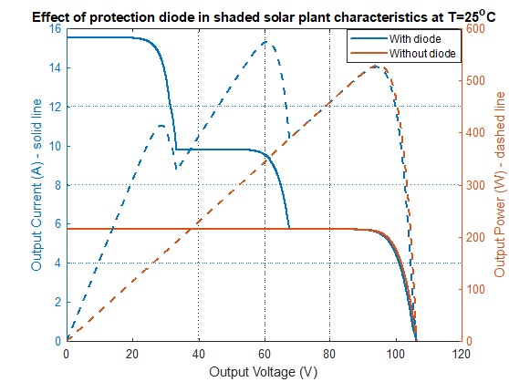
The plot below shows the I-V and P-V curve of the solar plant with different irradiance (irradianceMat) across the solar PV modules with only bypass diodes. The junction temperature is assumed to be uniform across the solar plant. The plot and table below show the improvement in the maximum output power. Many local output power maxima are observed with bypass diode. This effect is very important while evaluating the performance of the Maximum Power Point Tracking (MPPT) algorithm.
The plot below shows that near the highest voltage (large resistive load), all three PV modules in the solar PV strings are supplying power. In the middle voltage range, the PV module with the lowest irradiance, the third PV module in the PV string, got bypassed. In the lower voltage range (low resistance load) only PV modules with highest irradiance supplies power. In this example, this is the first PV module that supplies power to the load, remaining two PV modules are bypassed by the diode.
Cell junction temperature in degC, maximum power point current in A, voltage in V and Power in W
    JuntionTemperature    MaximumCurrent    MaximumVoltage    MaximumPower
    __________________    ______________    ______________    ____________

            25                9.4275            61.518           579.96
            50                9.3418            55.307           516.66

Solar Plant I-V Characteristics with Shading and Both Protection Diodes
The plot below shows the I-V and P-V curve of the solar plant with different irradiance (irradianceMat) across the solar PV modules with both bypass and blocking protection diodes. The junction temperature is assumed to be uniform across the solar plant. In this case, there is a reduction in voltage due to voltage drop across the blocking diode. This effect also reduces the maximum output power.
Cell junction temperature in degC, maximum power point current in A, voltage in V and Power in W
    JuntionTemperature    MaximumCurrent    MaximumVoltage    MaximumPower
    __________________    ______________    ______________    ____________

            25                9.4227            60.944           574.26
            50                9.3358            54.737           511.01

Shaded Solar Plant Characteristics with and Without Protection Diodes
The plot below shows the I-V and P-V curve of the solar plant with and without protection diode. Protection diodes improves the output power but characteristics has many local output power maxima.

Results from Real-Time Simulation
This example has been tested on a Speedgoat Performance real-time target machine with an Intel® 3.5 GHz i7 multi-core CPU. This model can run in real time with a step size of 70 microseconds.