Author Architecture Models Through Sequence Diagrams
You can use the co-creation and synchronization workflows in the Architecture Views Gallery to check and maintain consistency between a System Composer™ architecture model and its corresponding sequence diagram. These workflows allow you to:
Co-create components, ports, and connectors in your architecture model as you create new lifelines and messages in your sequence diagram.
Iteratively check consistency between your architecture and corresponding sequence diagrams.
For more information about sequence diagram topics, see Describe System Behavior Using Sequence Diagrams.
Traffic Light Example
Use sequence diagrams integrated with System Composer to efficiently describe system behaviors while creating architecture models. The co-creation workflow between the sequence diagram and the architecture model keeps the model synchronized as you make changes to the sequence diagram. Adding lifelines and messages in a sequence diagram results in updates to the architecture model.
In this example, you use the co-creation workflow with an architecture model and sequence diagrams that describe the scenario of a pedestrian crossing the street at an intersection with traffic lights.
Note
This example is different than the example in Author Sequence Diagrams Interactively. The
TrafficLight architecture model contains subsystems and root
architecture ports to show child lifelines and gates.
Open Sequence Diagram for Traffic Light Architecture
This traffic light example contains sequence diagrams to describe pedestrians crossing an intersection. The model describes these steps:
The traffic signal cycles from green to yellow to red.
When the pedestrian crossing button is pressed, if the traffic signal is green, the traffic signal transitions from yellow to red for a limited time.
The pedestrians cross while the walk signal is active.
Open the architecture model.
model = systemcomposer.openModel("TrafficLight");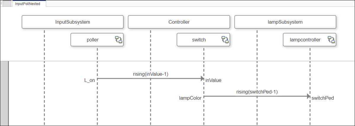
This architecture model has a sequence diagram called InputPollNested. Open the diagram in the Architecture Views Gallery.
interaction = model.getInteraction("InputPollNested");
open(interaction)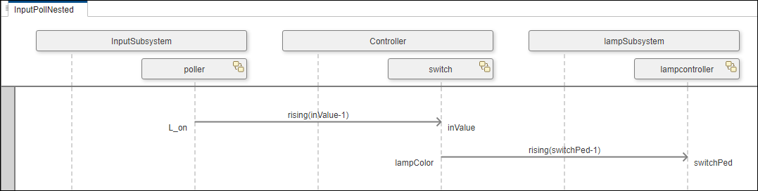
The InputPollNested interaction specifies this sequence of message events.
The
pollerlifeline recognizes a signal event asinValuerises to1, the pedestrian crossing button is pressed.The
switchlifeline recognizes a signal event to thelampcontrollerlifeline asswitchPedrises to1, which activates the pedestrian walk signal.
To describe another scenario with interactions, the TrafficLight architecture model also has a sequence diagram called PedLoop.
interaction1 = model.getInteraction("PedLoop");
open(interaction1)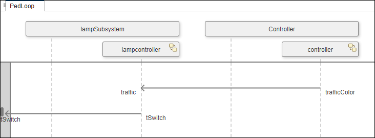
Create Architectural Elements By Describing Interactions
A sequence diagram is a visual representation of an interaction. An interaction specifies how each part of a system should interact as a sequence of message exchanges. You can represent elements of an interaction using lifelines, messages, fragments, and operands in sequence diagrams.
Add Lifelines to Create Components
A lifeline represents an instance of a component as a participant of an interaction. You can add lifelines to your sequence diagram to create new components in your architecture model.
From the toolstrip menu, select Component > Add Lifeline. Another box with a vertical dotted line appears on the canvas to represent a lifeline. In the box, enter the name of a new component named
Machine.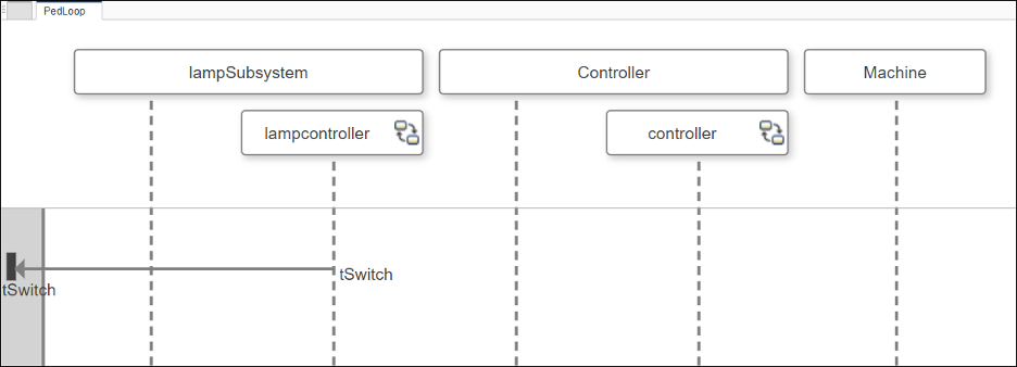
Observe that the
Machinecomponent is now in the architecture model.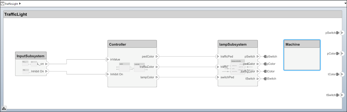
Add Messages to Create Connectors and Ports
A message represents communication between two lifelines. Messages have labels to specify the expected condition for the message to occur. You can add messages to your sequence diagram to create new connections in your architecture model.
A message end represents one of the ends of a message in an interaction. When you add a message to a sequence diagram, you can either select an existing port as a message end or you can create a new port.
You can modify the source and destination of a message after the message has been created. Click the
trafficColormessage end to select it.Click and drag the
trafficColormessage end to theControllerparent lifeline. Select thetrafficColorport.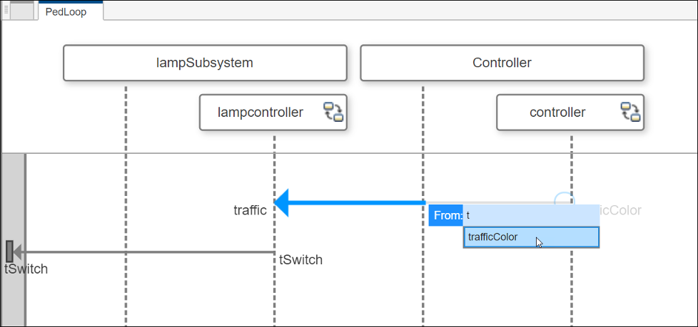
Once the
trafficColorport is selected, the message end moves from thecontrollerchild lifeline to theControllerparent lifeline.You can also rename message ends and the associated ports by double-clicking the name of a message end.
Maintain Consistency By Synchronizing Sequence Diagrams and Architectures
The co-creation workflow updates the architecture model based on changes you make in corresponding sequence diagrams. When elements are out of sync, you can use the synchronization workflow to check consistency. The software highlights any inconsistent elements in the sequence diagram.
The synchronization workflow in this section uses the TrafficLight
architecture model and the PedLoop sequence diagram.
Remove the
Machinecomponent from the architecture model.Return to the sequence diagram and select Synchronize > Check Consistency. See that the
Machinelifeline is highlighted because theMachinecomponent does not exist in the architecture model.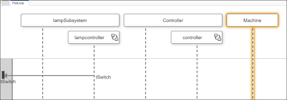
To restore consistency, you can either select Create in Architecture or remove the
Machinelifeline.To confirm the inconsistency is resolved, click Check Consistency again.
For advanced sequence diagram synchronization techniques, see Synchronize Sequence Diagrams and Architecture Models.
Link Elements of Sequence Diagram to Requirements
Since R2023a
You can link an entire sequence diagram or individual elements of a sequence diagram to requirements in the Architecture Views Gallery. A Requirements Toolbox™ license is required.
In sequence diagrams, links from lifelines and gates to requirements connect to the corresponding architectural elements.
To link elements to requirements:
To open the Requirements Editor (Requirements Toolbox), on the Views tab, in the Requirement section, click Open Requirements Editor. From here, you can author requirements, create requirement sets, and organize requirements into hierarchies.
With the Requirements Editor open, select the sequence diagram element that you want to link to a requirement. To select a lifeline, gate, fragment, message, or duration constraint, click the element on the sequence diagram canvas. To select the entire sequence diagram, click the name of the sequence diagram in the View Browser pane.
In the Requirements Editor, click the requirement that you want to link the selected sequence diagram element to.
You can link from the selected sequence diagram element to the requirement one of three ways.
In the Architecture Views Gallery, on the Views tab, in the Requirement section, click Link to selected requirement.
In the Requirements Editor, right-click the selected requirement and click Link from for the specific sequence diagram element.
In the Requirements Editor, click Add Link and select Link from for the specific sequence diagram element.
Note
You can create implemented links by linking lifelines and gates to requirements that correspond to architectural elements. If you delete an architectural element corresponding to a lifeline or gate, then the option to link a requirement from this element is disabled. If you delete an element after linking to a requirement, then the link is invalid.
You can create verified links by locally linking sequence diagrams, messages, and fragments link to the respective element in the sequence diagram.
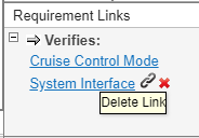
To view the requirements linked from sequence diagram elements, select an element on the sequence diagram. In the Views tab, in the Requirement section, click Requirements Manager. The requirements linked from the selected element are listed in the Requirement Links pane that appears at the bottom of the window.
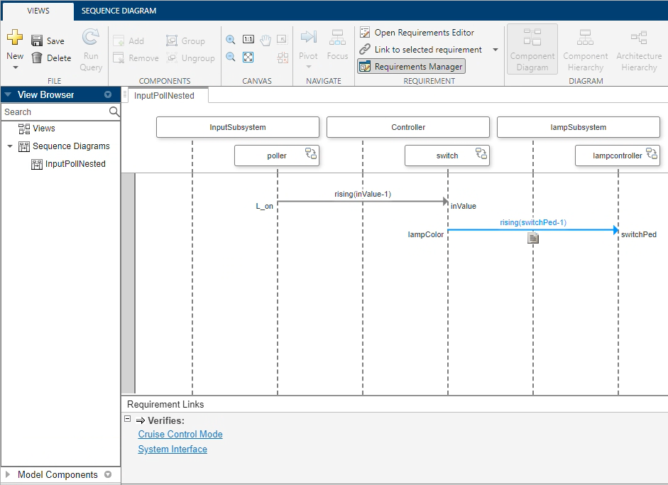
If the Requirements Manager button is pressed, then a gray
badge appears over each sequence diagram element that is linked to a requirement. To
display the corresponding requirement ID and the requirement
Summary text, point to the badge.
To view these requirements in the Requirements Editor, point to the
requirements in the Requirement Links pane and click the
Show in Links View
![]() button. You can delete requirement links from
sequence diagram elements by pausing your cursor on the requirement name, and clicking
the Delete Link
button. You can delete requirement links from
sequence diagram elements by pausing your cursor on the requirement name, and clicking
the Delete Link
![]() button.
button.