C2000 PID Controller
Digital PID controller
Description
Replace the existing DMC blocks with MCB blocks for improved usability and future compatibility. It is recommended that you use blocks from Control Algorithm Design (Motor Control Blockset). While these blocks are not one-to-one replacements, they enable you to achieve the same functionality.
| C28x DMC lib | C28x DMC lib equivalent in MCB |
|---|---|
| C2000 Clarke Transformation | Clarke Transform (Motor Control Blockset) |
| C2000 Inverse Park Transformation | Inverse Park Transform (Motor Control Blockset) |
| C2000 Park Transformation | Park Transform (Motor Control Blockset) |
| C2000 PID Controller | PI Controller (Motor Control Blockset) |
| C2000 Ramp Control | Position Generator (Motor Control Blockset) |
| C2000 Ramp Generator | Position Generator (Motor Control Blockset) |
| C2000 Space Vector Generator | PWM Reference Generator (Motor Control Blockset) |
| C2000 Speed Measurement | Speed Measurement (Motor Control Blockset) |
This block implements a 32-bit digital PID controller with antiwindup
correction. The inputs are a reference input (ref) and a feedback input
(fdb) and the output (out) is the saturated PID
output. The following diagram shows a PID controller with antiwindup.
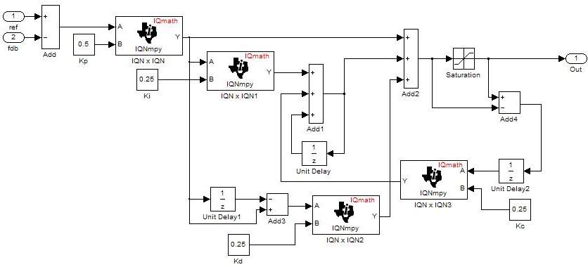
The differential equation describing the PID controller before saturation that is implemented in this block is
| upresat(t) = up(t) + ui(t) + ud(t) | (1) |
where upresat is the PID output before saturation, up is the proportional term, ui is the integral term with saturation correction, and ud is the derivative term.
The proportional term is
| up(t) = Kpe(t) | (2) |
where Kp is the proportional gain of the PID controller and e(t) is the error between the reference and feedback inputs.
The integral term with saturation correction is
![]()
where Kc is the integral correction gain of the PID controller.
The derivative term is
![]()
where Td is the derivative time of the PID controller. In discrete terms, the derivative gain is defined as Kd = Td/T, and the integral gain is defined as Ki = T/Ti, where T is the sampling period and Ti is the integral time of the PID controller.
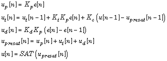
Using backward approximation, the preceding differential equations can be transformed into the following discrete equations.
Note
To generate optimized code from this block, enable the
TI C28xorTI C28x (ISO)Code Replacement Library.The implementation of this block does not call the corresponding Texas Instruments® library function during code generation. The TI function uses a global Q setting and the MathWorks® code used by this block dynamically adjusts the Q format based on the block input. See Using the IQmath Library for more information.
This block implements a 32-bit digital PID controller with antiwindup
correction. The inputs are a reference input (ref) and a feedback input
(fdb) and the output (out) is the saturated PID
output. The following diagram shows a PID controller with antiwindup.
The differential equation describing the PID controller before saturation that is implemented in this block is
| upresat(t) = up(t) + ui(t) + ud(t) | (3) |
where upresat is the PID output before saturation, up is the proportional term, ui is the integral term with saturation correction, and ud is the derivative term.
The proportional term is
| up(t) = Kpe(t) | (4) |
where Kp is the proportional gain of the PID controller and e(t) is the error between the reference and feedback inputs
![]()
where Kc is the integral correction gain of the PID controller.
The derivative term is
![]()
where Td is the derivative time of the PID controller. In discrete terms, the derivative gain is defined as Kd = Td/T, and the integral gain is defined as Ki = T/Ti, where T is the sampling period and Ti is the integral time of the PID controller.
Using backward approximation, the preceding differential equations can be transformed into the following discrete equations.
Note
To generate optimized code from this block, enable the
TI C28xorTI C28x (ISO)Code Replacement Library.The implementation of this block does not call the corresponding Texas Instruments library function during code generation. The TI function uses a global Q setting and the MathWorks code used by this block dynamically adjusts the Q format based on the block input. See Using the IQmath Library for more information.
Parameters
- Proportional gain
Amount of proportional gain (Kp) to apply to the PID
- Integral gain
Amount of gain (Ki) to apply to the integration equation
- Integral correction gain
Amount of correction gain (Kc) to apply to the integration equation
- Derivative gain
Amount of gain (Kd) to apply to the derivative equation.
- Minimum output
Minimum allowable value of the PID output
- Maximum output
Maximum allowable value of the PID output
References
For detailed information on the DMC library, see C/F 28xx Digital Motor Control Library, Literature Number SPRC080, available at the Texas Instruments Web site.