C28x-GPIO
Use the GPIO pins for digital input or output by connecting to one of the three peripheral I/O ports.
The GPIO pins available for various processors are:
| Processors | GPIO Pin Values |
|---|---|
| C281x | GPIOA, GPIOB, GPIOD, GPIOE, GPIOF, and GPIOG. |
| F2803x | GPIO0_7, GPIO8_15, GPIO16_23, GPIO24_31, GPIO32_39, and GPIO40_44. |
| F2805x | GPIO0_7, GPIO8_15, GPIO16_23, GPIO24_31, GPIO32_39, and GPIO40_42. |
| F2806x | GPIO0_7, GPIO8_15, GPIO16_23, GPIO24_31, GPIO32_39, GPIO40_44, GPIO50_55, and GPIO56_58. |
| F2823x, F2833x, and C2834x | GPIO0_7, GPIO8_15, GPIO16_23, GPIO24_31, GPIO32_39, GPIO40_47, GPIO48_55, and GPIO56_63. |
| C2801x, F2802x, F28044, F280x | GPIO0_7, GPIO8_15, GPIO16_23, GPIO24_31, and GPIO32_34. |
| F28M35x (C28x) | GPIO0_7, GPIO8_15, GPIO16_23, GPIO24_31, GPIO32_39, GPIO40_47, GPIO48_55, GPIO56_63, GPIO68_71, and GPIO128_135. |
| F28M36x (C28x) | GPIO0_7, GPIO8_15, GPIO16_23, GPIO24_31, GPIO40_47, GPIO48_55, GPIO56_63, GPIO64_71, GPIO72_79, GPIO80_87, GPIO88_95, GPIO96_103, GPIO104_111, GPIO112_119, GPIO120_127, GPIO128_135, and GPIO192_199. |
| F2807x | GPIO0_7, GPIO8_15, GPIO16_23, GPIO24_31, GPIO40_47, GPIO48_55, GPIO56_63, GPIO64_71, GPIO72_79, GPIO80_87, GPIO88_95, GPIO96_103, and GPIO128_135. |
| F2837xD | GPIO0_7, GPIO8_15, GPIO16_23, GPIO24_31, GPIO40_47, GPIO48_55, GPIO56_63, GPIO64_71, GPIO72_79, GPIO80_87, GPIO88_95, GPIO96_103, GPIO104_111, GPIO112_119, GPIO120_127, GPIO128_135, GPIO136_143, GPIO144_151, GPIO152_159, GPIO160_167, and GPIO168_175. |
| F2837xS | GPIO0_7, GPIO8_15, GPIO16_23, GPIO24_31, GPIO40_47, GPIO48_55, GPIO56_63, GPIO64_71, GPIO72_79, GPIO80_87, GPIO88_95, GPIO96_103, GPIO104_111, GPIO112_119, GPIO120_127, GPIO128_135, GPIO136_143, GPIO144_151, GPIO152_159, GPIO160_167, and GPIO168_175. |
| F2838x | GPIO0_7, GPIO8_15, GPIO16_23, GPIO24_31, GPIO40_47, GPIO48_55, GPIO56_63, GPIO64_71, GPIO72_79, GPIO80_87, GPIO88_95, GPIO96_103, GPIO104_111, GPIO112_119, GPIO120_127, GPIO128_135, GPIO136_143, GPIO144_151, GPIO152_159, GPIO160_167, and GPIO168_175. |
| F28004x | GPIO0_7, GPIO8_15, GPIO16_23, GPIO24_31, GPIO32_39, GPIO40_47, GPIO48_55, and GPIO56_63. |
Each pin selected for input offers four signal qualification types:
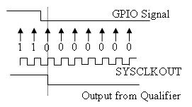
Synchronize to SYSCLKOUT only—This setting is the default for all pins at reset. Using this qualification type, the input signal is synchronized to the system clock, SYSCLKOUT. The following figure shows the input signal measured on each tick of the system clock, and the resulting output from the qualifier.
Qualification using 3 samples—This setting requires three consecutive cycles of the same value for the output value to change. The following figure shows that, in the third cycle, the GPIO value changes to0, but the qualifier output is still1because it waits for three consecutive cycles of the same GPIO value. The next three cycles have a value of0, and the output from the qualifier changes to0immediately after the third consecutive value is received.
Qualification using 6 samples—This setting requires six consecutive cycles of the same GPIO input value for the output from the qualifier to change. In the following figure, glitch A does not alter the output signal. When the glitch occurs, the counting begins, but as the next measurement is low again, the count is ignored. The output signal does not change until six consecutive samples of the high signal are measured.
Note
These GPIO settings are supported for the F2837xD dual core processor only when you select
CPU1in Build options >Select CPU.Qualification sampling period
Visible only when the
Qualification using #
                              samples
option is selected. The qualification sampling period, with possible values of0–255, inclusive, calculates the frequency of the qualification samples or the number of system clock ticks per sample. The formula for calculating the qualification sampling frequency is SYSCLKOUT/(2 * Qualification sampling period), except for zero. When Qualification sampling period=0, a sample is taken every SYSCLKOUT clock tick. For example, a setting of0means that a sample is taken on each SYSCLKOUT tick.The following figure shows the SYSCLKOUT ticks, a sample taken every clock tick, and the Qualification type set to
Qualification using 3 samples. In this case, the Qualification sampling period=0:
In the next figure Qualification sampling period
=1. A sample is taken every two clock ticks, and the Qualification type is set toQualification using 3 samples. The output signal changes much later than if Qualification sampling period=0.
In the following figure, Qualification sampling period
=2. A sample is taken every four clock ticks, and the Qualification type is set toQualification using 3 samples.
Asynchronous—Using this qualification type, the signal is synchronized to an asynchronous event initiated by the software (CPU) via control register bits.
GPIOA, GPIOB, GPIOD, GPIOE input qualification sampling period
GPIO# Pull Up Disabled
Select this check box to disable the GPIO pull-up register. This option is available only for TI Concerto F28M35x/F28M36x processors.