Noise Removal and Image Sharpening
This example shows how to use Vision HDL Toolbox™ to implement an FPGA-based module for image enhancement.
Vision HDL Toolbox provides video processing algorithms designed to generate readable, synthesizable code in VHDL and Verilog (with HDL Coder™). The generated HDL code can process 1080p video at a rate of 60 frames per second.
The Computer Vision Toolbox™ product models at a high level of abstraction. The blocks and objects perform full-frame processing, operating on one image frame at a time. However, FPGA or ASIC systems perform pixel-stream processing, operating on one image pixel at a time.
Input images from physical systems frequently contain impairments such as blur and noise. An object out of focus results in a blurred image. Dead or stuck pixels on the camera or video sensor, or thermal noise from hardware components, contribute to the noise in the image. This example removes noise and sharpens the input image, and it can be used at an early stage of the processing chain to provide a better initial condition for subsequent processing. This example uses two pixel-stream filter blocks from the Vision HDL Toolbox. The median filter removes the noise and the image filter sharpens the image. To verify the pixel-stream design, the results are compared with those generated by the full-frame blocks from the Computer Vision Toolbox.
Model Overview
The NoiseRemovalAndSharpeningHDLExample.slx system is shown.
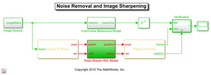
Computer Vision Toolbox blocks operate on an entire frame at a time. Vision HDL Toolbox blocks operate on a stream of pixel data, one pixel at a time. The conversion blocks in Vision HDL Toolbox, Frame To Pixels and Pixels To Frame, enable you to simulate streaming-pixel designs and to compare with full-frame designs.
The difference in the color of the lines feeding the Full-Frame Behavioral Model and Pixel-Stream HDL Model subsystems indicates the change in the image rate on the streaming branch of the model. This rate transition occurs because the pixel stream is sent out in the same amount of time as the full video frames and therefore it is transmitted at a higher rate. To turn on colors and view sample time information, in the left palette, click the Sample Time icon and select Colors.
The following figure shows the Image Source subsystem.
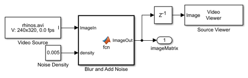
The Image Source block imports a greyscale image, then uses a MATLAB function block named Blur and Add Noise to blur the image and inject salt-and-pepper noise. The imfilter function uses a 3-by-3 averaging kernel to blur the image. The salt-and-pepper noise is injected by calling the imnoise command. The noise density is defined as the ratio of the combined number of salt and pepper pixels to the total pixels in the image. This density value is specified by the Noise Density constant block, and it must be between 0 and 1. The Image Source subsystem outputs a 2-D matrix of a full-frame image.
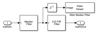
The diagram below shows the structure of the Full-Frame Behavioral Model subsystem, which consists of the frame-based Median Filter and 2-D FIR Filter from Computer Vision Toolbox. Median filter removes the noise and 2-D FIR Filter is configured to sharpen the image.
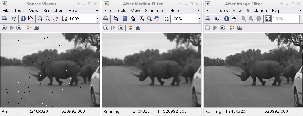
The displays below show one frame of the blurred and noisy source video, its de-noised version after median filtering, and the sharpened output after 2-D FIR filtering.
The Pixel-Stream HDL Model subsystem uses Vision HDL Toolbox to implement streaming based median filter and 2-D FIR filter. The Verification subsystem compares the results from full-frame processing with those from pixel-stream processing. These two subsystems are described in the next two sections.
Pixel-Streaming HDL Design
The Frame To Pixels block converts a full-frame image to a pixel stream since blocks in Vision HDL Toolbox operate on stream input signals required by FPGA hardware. To simulate the effect of horizontal and vertical blanking periods found in video systems based on FPGAs or ASICs, the active image is augmented with non-image data. For more information on the streaming pixel protocol, see the Streaming Pixel Interface (Vision HDL Toolbox). The Frame To Pixels block is configured as shown:
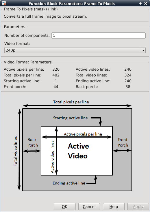
The Number of components field is set to 1 for grayscale image input, and the Video format field is 240p to match that of the video source.
In this example, the Active Video region corresponds to the 240x320 matrix of the blurred and noisy image from the upstream Image Source subsystem. Six other parameters, namely, Total pixels per line, Total video lines, Starting active line, Ending active line, Front porch, and Back porch specify how many non-image pixels will be added on the four sides of the Active Video. For more information, see the Frame To Pixels (Vision HDL Toolbox) block reference page.
Note that the Desired sample time of the Video Source inside Image Source is determined by the product of Total pixels per line and Total video lines.
The Pixel-Stream HDL Model subsystem contains the streaming implementation of the median filter and 2-D FIR filter from Vision HDL Toolbox, as shown in the diagram below. You can generate HDL code from the Pixel-Stream HDL Model subsystem using HDL Coder™.
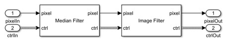
The Median Filter (Vision HDL Toolbox) block is used to remove the salt and pepper noise. Based on the filter coefficients, the Image Filter (Vision HDL Toolbox) block can be used to blur, sharpen, or detect the edges of the recovered image after median filtering. In this example, Image Filter is configured to sharpen an image.
Verifying the Pixel-Stream Processing Design
In order to compare with the output of the full-frame filters from the Computer Vision Toolbox, the model converts the pixel stream data back to full frame using the Pixels To Frame block. The Number of components field and the Video format fields of both Frame To Pixels and Pixels To Frame are set at 1 and 240p, respectively, to match the format of the video source.
The output of the Pixels To Frame block is a 2-D matrix of a full image. This allows us to compare the HDL model against the behavioral model in the full-frame domain, as shown in the Verification subsystem shown below.
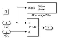
The peak signal to noise ratio (PSNR) is calculated between the reference image and the stream processed image. Ideally, the ratio should be inf, indicating that the output image from the Full-Frame Behavioral Model matches that generated from the Pixel-Stream HDL Model.
Generate HDL Code and Verify Its Behavior
To check and generate the HDL code referenced in this example, you must have an HDL Coder license.
To generate the HDL code, use the following command:
makehdl('NoiseRemovalAndSharpeningHDLExample/Pixel-Stream HDL Model');
To generate test bench, use the following command:
makehdltb('NoiseRemovalAndSharpeningHDLExample/Pixel-Stream HDL Model');
Select a Web Site
Choose a web site to get translated content where available and see local events and offers. Based on your location, we recommend that you select: United States.
You can also select a web site from the following list
Americas
- América Latina (Español)
- Canada (English)
- United States (English)
Europe
- Belgium (English)
- Denmark (English)
- Deutschland (Deutsch)
- España (Español)
- Finland (English)
- France (Français)
- Ireland (English)
- Italia (Italiano)
- Luxembourg (English)
- Netherlands (English)
- Norway (English)
- Österreich (Deutsch)
- Portugal (English)
- Sweden (English)
- Switzerland
- United Kingdom (English)