Corner Detection
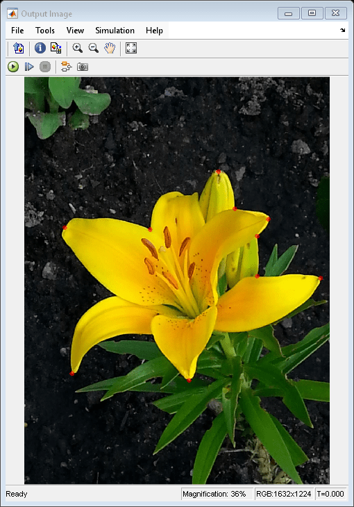
Calculate corner metric matrix and find corners in images
Libraries:
Computer Vision Toolbox /
Analysis & Enhancement
Description
The Corner Detection block finds corners in an image by using the Harris corner detection (by Harris and Stephens), minimum eigenvalue (by Shi and Tomasi), or local intensity comparison (based on the Accelerated Segment Test, (FAST) method by Rosten and Drummond) method. The block finds the corners in the image based on the pixels that have the largest corner metric values.
Examples
Ports
Input
I — Input image
matrix of intensity values
Input image, specified as a matrix of intensity values.
Data Types: single
| double
| int8
| int16
| int32
| int64
| uint8
| uint16
| uint32
| uint64
| fixed point
Output
Loc — Corner locations
M-by-2 matrix
Corner locations, returned as an M-by-2 matrix of [x y] coordinates. M represents the number of corners and is less than or equal to the Maximum number of corners parameter.
Dependencies
To enable this port, set the Output parameter to one of these:
Corner location
Corner location and metric matrix
Data Types: uint32
Count — Number of detected corners
scalar
Number of detected corners, returned as a scalar.
Dependencies
To enable this port, set these block parameters:
Output:
Corner location
|Corner location and metric matrix
Output variable size signal:
off
Data Types: uint32
Metric — Corner metric values
matrix
Corner metric values, returned as a matrix of intensity values. The returned matrix is the same size as the input image.
Dependencies
To enable this port, set the Output parameter to one of these:
Corner location and metric matrix
Metric matrix
Data Types: single
| double
| int8
| int16
| int32
| int64
| uint8
| uint16
| uint32
| uint64
| fixed point
Parameters
Main
Method — Corner detection method
Harris corner detection (Harris &
Stephens)
(default) | Minimum eigenvalue (Shi & Tomasi)
| Local intensity comparison (Rosten &
Drummond)
Specify the corner detection method as Harris corner detection
(Harris & Stephens)
, Minimum eigenvalue (Shi &
Tomasi)
, or Local intensity comparison (Rosten &
Drummond)
.
To get the most accurate results, use Minimum eigenvalue (Shi &
Tomasi)
. For the fastest computation, use Local intensity
comparison (Rosten & Drummond)
. For a balance between accuracy and
computation speed, use Harris corner detection (Harris &
Stephens)
. For more information on each method, see the Algorithms section.
Sensitivity factor (0<k<0.25) — Sensitivity factor
0.04 (default) | scalar
Specify the sensitivity factor, k. As k decreases, the likelihood that the algorithm can detect sharp corners increases.
Tunable: Yes
Dependencies
To enable this parameter, set the Method parameter to
Harris corner detection (Harris & Stephens)
.
Coefficients for separable smoothing filter — Filter coefficients
fspecial('gaussian', [1 5], 1.5) (default) | vector
Specify a vector of filter coefficients for the smoothing filter.
Dependencies
To enable this parameter, set the Method parameter to one of these:
Harris corner detection (Harris & Stephens)
Minimum eigenvalue (Shi & Tomasi)
Intensity comparison threshold — Intensity threshold
0.1 (default) | scalar
Specify the intensity threshold value used to find valid surrounding pixels.
Tunable: Yes
Dependencies
To enable this parameter, set the Method parameter to
Local intensity comparison (Rosten &
Drummond)
.
Maximum angle to be considered a corner (in degrees) — Maximum corner angle
157.5 (default) | scalar
Specify the maximum corner angle.
Tunable: Yes
Dependencies
To enable this parameter, set the Method parameter to
Local intensity comparison (Rosten & Drummond)
.This parameter is tunable for simulation only.
Output — Block output
Corner location
(default) | Corner location and metric matrix
| Metric matrix
Specify the block output as Corner location
,
Corner location and metric matrix
, and
Metric matrix
.
Set this parameter to Corner location
or
Corner location and metric matrix
to expose the
Maximum number of corners, Minimum metric value that
indicates a corner, and Neighborhood size (suppress region
around detected corners) parameters.
Maximum number of corners — Maximum number of corners
200 (default) | integer
Specify the maximum number of corners you want the block to find.
Dependencies
To enable this parameter, set the Output parameter to one of these:
Corner location
Corner location and metric matrix
Minimum metric value that indicates a corner — Minimum corner metric
0.0005 (default) | scalar
Specify the minimum corner metric value.
Tunable: Yes
Dependencies
To enable this parameter, set the Output parameter to one of these:
Corner location
Corner location and metric matrix
Neighborhood size — Neighborhood size
[11 11] (default) | 2-element vector
Specify the neighborhood size as a two-element vector of positive odd integers, [row, column]. The block uses this parameter to suppress the region around a valid corner point with the largest corner metric value.
Dependencies
To enable this parameter, set the Output parameter to one of these:
Corner location
Corner location and metric matrix
Output variable size signal — Variable size signal
on
(default) | off
Select this parameter to output a variable size signal.
Dependencies
To enable this parameter, set the Output parameter to one of these:
Corner location
Corner location and metric matrix
Data Types
For details on the fixed-point block parameters, see Specify Fixed-Point Attributes for Blocks (DSP System Toolbox).
Lock data type settings against change by the fixed-point tools — Data type override
off
(default) | on
Select this parameter to prevent the fixed-point tools from overriding the data types you specify in this block. For more information, see Lock the Output Data Type Setting (Fixed-Point Designer).
Block Characteristics
More About
These diagrams show the data types used in the Corner Detection block for fixed-point signals. These diagrams apply to the Harris corner detection and minimum eigenvalue methods only.
The following table summarizes the variables used in the previous diagrams.
Variable Name | Definition |
---|---|
IN_DT | Input data type |
MEM_DT | Memory data type |
OUT_DT | Metric output data type |
COEF_DT | Coefficients data type |
Algorithms
Determine final corner values
To determine the final corner values, the block follows this process:
Find the pixel with the largest corner metric value.
Verify that the metric value is greater than or equal to the value you specified for the Minimum metric value that indicates a corner parameter.
Suppress the region around the corner value by the size defined in the Neighborhood size (suppress region around detected corners) parameter.
The block repeats this process until it finds all the corners in the image or it finds the number of corners you specified in the Maximum number of corners parameter.
The corner metric values computed by the Minimum eigenvalue
and Local intensity comparison
methods are always nonnegative.
The corner metric values computed by the Harris corner detection
method can be negative.
Minimum Eigenvalue Method
The method is more computationally expensive than the Harris corner detection algorithm because it directly calculates the eigenvalues of the sum of the squared difference matrix, M.
The sum of the squared difference matrix, M, is defined as follows:
The previous equation is based on the following values:
where and are the gradients of the input image, I, in the x and y direction. The symbol denotes a convolution operation.
Use the Coefficients for separable smoothing filter parameter to define a vector of filter coefficients. The block multiplies this vector of coefficients by its transpose to create a matrix of filter coefficients, w.
The block calculates the smaller eigenvalue of the sum of the squared difference matrix. This minimum eigenvalue corresponds to the corner metric matrix.
Harris Corner Method
The Harris corner detection method avoids the explicit computation of the eigenvalues of the sum of squared differences matrix by solving for the corner metric matrix, R:
See the Minimum Eigenvalue Method section for the definitions of A, B, and C.
The variable k corresponds to the sensitivity factor. You can specify its value using the Sensitivity factor (0<k<0.25) parameter. As k decreases, the likelihood that the algorithm can detect sharp corners increases.
Use the Coefficients for separable smoothing filter parameter to define a vector of filter coefficients. The block multiplies this vector of coefficients by its transpose to create a matrix of filter coefficients, w.
Local Intensity Method
The method determines that a pixel is a possible corner if it has either, N contiguous valid bright surrounding pixels, or N contiguous dark surrounding pixels.
Suppose that p is the pixel under consideration and j is one of the pixels surrounding p. The locations of the other surrounding pixels are denoted by the shaded areas in the following figure. The shaded areas in this figure denote the locations of other surrounding pixels.
and are the intensities of pixels p and j, respectively. Pixel j is a valid bright surrounding pixel if . Similarly, pixel j is a valid dark surrounding pixel if . In these equations, T is the value you specified for the Intensity comparison threshold parameter.
The block repeats this process to determine whether the block has N contiguous valid surrounding pixels. The value of N is related to the value you specify for the Maximum angle to be considered a corner (in degrees) parameter, as shown in this table.
Number of Valid Surrounding Pixels and Angle
Number of Valid Surrounding Pixels | Angle (degrees) |
---|---|
15 | 22.5 |
14 | 45 |
13 | 67.5 |
12 | 90 |
11 | 112.5 |
10 | 135 |
9 | 157.5 |
After the block determines that a pixel is a possible corner, it computes its corner metric using the following equation:
References
[1] Harris, C. and M Stephens. “A Combined Corner and Edge Detector.” Proceedings of the 4th Alvey Vision Conference, 147-151. August 1988.
[2] Shi, J. and C. Tomasi. “Good Features to Track.” Proceedings of the IEEE Conference on Computer Vision and Pattern Recognition, 593-600. June 1994.
[3] Rosten, E. and T. Drummond. “Fusing Points and Lines for High Performance Tracking.” Proceedings of the IEEE International Conference on Computer Vision Vol. 2, 1508-1511. October 2005.
Extended Capabilities
C/C++ Code Generation
Generate C and C++ code using Simulink® Coder™.
Fixed-Point Conversion
Design and simulate fixed-point systems using Fixed-Point Designer™.
Version History
Introduced in R2007b
See Also
Blocks
Functions
MATLAB Command
You clicked a link that corresponds to this MATLAB command:
Run the command by entering it in the MATLAB Command Window. Web browsers do not support MATLAB commands.
Select a Web Site
Choose a web site to get translated content where available and see local events and offers. Based on your location, we recommend that you select: .
You can also select a web site from the following list
How to Get Best Site Performance
Select the China site (in Chinese or English) for best site performance. Other MathWorks country sites are not optimized for visits from your location.
Americas
- América Latina (Español)
- Canada (English)
- United States (English)
Europe
- Belgium (English)
- Denmark (English)
- Deutschland (Deutsch)
- España (Español)
- Finland (English)
- France (Français)
- Ireland (English)
- Italia (Italiano)
- Luxembourg (English)
- Netherlands (English)
- Norway (English)
- Österreich (Deutsch)
- Portugal (English)
- Sweden (English)
- Switzerland
- United Kingdom (English)
Asia Pacific
- Australia (English)
- India (English)
- New Zealand (English)
- 中国
- 日本Japanese (日本語)
- 한국Korean (한국어)