Edge Detector
Find edges of objects in grayscale pixel stream
Libraries:
Vision HDL Toolbox /
Analysis & Enhancement
Description
The Edge Detector block finds the edges in a grayscale pixel stream by using the Sobel, Prewitt, or Roberts method. The block convolves the input pixels with derivative approximation matrices to find the gradient of pixel magnitude along two orthogonal directions. It then compares the sum of the squares of the gradients to the square of a configurable threshold to determine if the gradients represent an edge.
By default, the block returns a binary image as a stream of pixel values. A pixel value of 1 indicates that the pixel is an edge. You can disable the edge output. You can also enable output of the gradient values in the two orthogonal directions at each pixel.
Examples
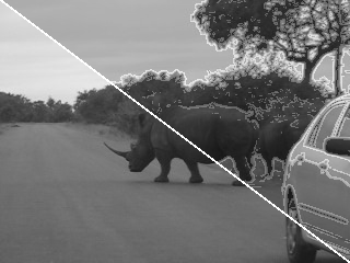
Edge Detection and Image Overlay
Detect and highlight object edges in a video stream.
Filter Multipixel Video Streams
Design filters that operate on a multipixel input video stream. Use multipixel streaming to process high-resolution or high-frame-rate video with the same synthesized clock frequency as a single-pixel streaming interface. Multipixel streaming also improves simulation speed and throughput because fewer iterations are required to process each frame, while maintaining the hardware benefits of a streaming interface.
Ports
This block uses a streaming pixel interface with a
bus for frame control signals. This interface enables the block to operate independently
of image size and format. The pixel, Edge, and
gradient ports on this block support single pixel streaming or multipixel streaming.
Single pixel streaming accepts and returns a single pixel value each clock cycle.
Multipixel streaming accepts and returns a vector of M pixels per
clock cycle to support high-frame-rate or high-resolution formats. The
M value corresponds to the Number of pixels
parameter of the Frame To Pixels block. Along with the pixel, the block
accepts and returns a pixelcontrol bus containing five control
signals. The control signals indicate the validity of each pixel and their location in
the frame. For multipixel streaming, one set of control signals applies to all pixels in
the vector. To convert a frame (pixel matrix) into a serial pixel stream and control
signals, use the Frame To Pixels block. For a full
description of the interface, see Streaming Pixel Interface.
Input
Output
Parameters
Tips
When you use a block with an internal line buffer inside an Enabled Subsystem (Simulink), the enable signal pattern must maintain the timing of the pixel stream, including the minimum blanking intervals. If the enable pattern corrupts the timing of the pixel stream, you might see partial output frames, corrupted pixel stream control signals, or mismatches between Simulink® and HDL simulation results. You may need to extend the blanking intervals to accommodate for cycles when the enable is low. For more information, see Configure Blanking Intervals.
Algorithms
The Edge Detector block provides three methods for detecting edges in an input image. The methods use different derivative approximation matrices to find two orthogonal gradients. The Sobel and Prewitt methods calculate the gradient in horizontal and vertical directions. The Roberts method calculates the gradients at 45 degrees and 135 degrees. The block uses the same matrices as the Edge Detection block in Computer Vision Toolbox™.
When you use multipixel streaming, the block uses a single line memory and implements one filter for each of the M input pixels, in parallel. This increase in hardware resources is a trade off for increasing throughput compared to single-pixel streaming.
| Method | Direction 1 | Direction 2 |
|---|---|---|
| Sobel | ||
| Prewitt | ||
| Roberts |
Note
The Prewitt coefficients require extra bits of precision because they are not powers of two. The block uses 16 bits to represent the Prewitt coefficients. For 8-bit input, the default size of the full-precision gradients is 27 bits. When using the Prewitt method, a good practice is to reduce the word length used for the gradient calculation. Select the Output the gradient components check box, and then on the Data Types tab, specify a smaller word length using Gradient Data Type.
The block convolves the neighborhood of the input pixel with the derivative matrices, D1 and D2. It then compares the sum of the squares of the gradients to the square of the threshold. Computing the square of the threshold avoids constructing a square root circuit. The block casts the gradients to the type you specified on the Data Types tab. The type conversion on the square of the threshold matches the type of the sum of the squares of the gradients.

The latency of the block is the line buffer latency plus the
latency of the kernel calculation. The line buffer latency includes edge padding by default. The
latency of the padding operation depends on the size of the kernel. If edge padding is not
necessary for your design, you can reduce the latency by setting the Padding
method parameter to None. When you use this option, the block
latency does not depend on your kernel size. To determine the exact latency for any
configuration of the block, measure the number of time steps between the input and output
control signals.

Note
When you use edge padding, use a horizontal blanking interval of at least twice the kernel width. This interval lets the algorithm finish processing one line before it starts processing the next one, including adding padding pixels before and after the active pixels in the line.
The horizontal blanking interval is equal to TotalPixelsPerLine – ActivePixelsPerLine or, equivalently, FrontPorch + BackPorch. Standard streaming video formats use a horizontal blanking interval of about 25% of the frame width. This interval is much larger than the filters applied to each frame.
The horizontal blanking interval must also meet these minimums:
If the kernel size is less than 4, and you use edge padding, the total porch must be at least 8 pixels.
When you disable edge padding, the horizontal blanking interval must be at least 12 cycles and is independent of the kernel size.
The BackPorch must be at least 6 pixels. This parameter is the number of inactive pixels before the first valid pixel in a frame.
For more information, see Configure Blanking Intervals.
Extended Capabilities
Version History
Introduced in R2015aSee Also
Blocks
- Edge Detection (Computer Vision Toolbox) | Frame To Pixels
Objects
Functions
edge(Image Processing Toolbox)