LDPC Decoder
Libraries:
Wireless HDL Toolbox /
Error Detection and Correction
Description
The LDPC Decoder block implements a quasi-cyclic low-density parity-check (QC-LDPC) decoder with hardware-friendly control signals. The block accepts log-likelihood ratio (LLR) values and a stream of control signals and outputs decoded bits, a stream of control signals, and a signal that indicates whether the block is ready to accept new inputs.
This block provides an option to implement layered belief propagation with either the normalized min-sum approximation algorithm or the min-sum approximation algorithm. The LDPC Decoder block supports scalar and N-element column vector inputs with a specified parity-check matrix and block size. The block supports the early termination feature to help improve decoding performance and faster convergence speeds at high signal noise ratio (SNR) conditions. The block supports QC-LDPC codes of circulant weight 1.
The block enables decoding of multiple code rates to help achieve high throughput efficiency with a high degree of code rate flexibility. You can use this block to develop a standard-based or generalized receiver that uses a QC-LDPC for forward error correction (FEC) coding. The block provides an architecture suitable for HDL code generation and hardware deployment. For more information, see Algorithms.
Examples

LDPC Encode and Decode of Streaming Data
Use LDPC Encoder and LDPC Decoder blocks and verify their functionality.
Ports
Input
Output
Parameters
More About
QC-LDPC codes are an important class of codes within the family of LDPC codes. You can use LDPC codes in many applications because of their simple encoding implementation of using cyclic shift registers. The LDPC Encoder block performs encoding using a parity-check matrix.
The block supports matrices with a circulant weight of 1. Each element in the parity-check matrix corresponds to a submatrix of size Z. The elements in the parity-check matrix must be in the range [–1, Z –1], where Z is the block size. In a parity-check matrix, –1 corresponds to a zero submatrix, 0 corresponds to an identity submatrix, 1 corresponds to an identity submatrix circularly shifted by one time, and n corresponds a submatrix circularly shifted by n times, where n is any value in the range [0, Z – 1].
This figure shows a parity-check matrix of size 2-by-4 whose block size is 4.

In this parity-check matrix:
–1represents a zero submatrix, [0 0 0 0; 0 0 0 0; 0 0 0 0; 0 0 0 0].0represents an identity submatrix, [1 0 0 0; 0 1 0 0; 0 0 1 0; 0 0 0 1].1represents an identity submatrix circularly shifted by one time, [0 1 0 0; 0 0 1 0; 0 0 0 1;1 0 0 0].2represents an identity submatrix circularly shifted by two times, [0 0 1 0; 0 0 0 1; 1 0 0 0; 0 1 0 0].3represents an identity submatrix circularly shifted by three times, [0 0 0 1; 1 0 0 0; 0 1 0 0; 0 0 1 0].
Algorithms
This figure shows the architecture block diagram of the LDPC Decoder block. The Controller block controls the layer and iteration count of the decoding process. The Variable node RAM block stores the variable node (VN) messages, and Check node RAM block stores the check node messages (CN). The Functional Unit block calculates the variable node (VN) messages and check node (CN) messages based on the layered belief propagation and either the normalized min-sum approximation algorithm or the min-sum approximation algorithm. The Termination/Parity check status block calculates the parity checks and provides the parity check status after each iteration.
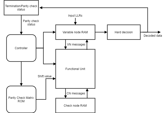
The implementation of the block matches the performance of the function ldpcDecode.
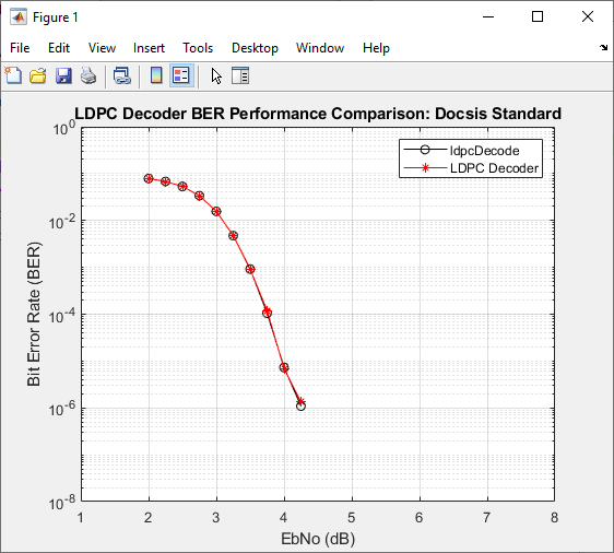
This plot shows the performance of block with a parity check matrix specified for a 4-bit
LLR input with a block length of 1120 in Docsis 3.1 standard, and when the
Algorithm parameter is set to Min-sum.
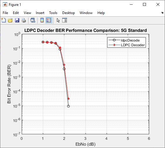
This plot shows the performance of block with a parity check matrix specified for a 4-bit
LLR input with bgn 1 and lifting size 384 in 5G NR standard, and when the
Algorithm parameter is set to
Min-sum.
The latency of the block varies with the Parity-check matrix parameter and the number of iterations. Because the latency varies, use the nextFrame control signal output port to determine when the block is ready for a new input frame.
The latency of the block is equal to r x (t +
m x 10) + (inputLen/vecSize)
+ 13. In this calculation, r is the number of iterations,
t is twice the total number of non –1 elements in the parity check
matrix, m is the number of rows in the parity check matrix,
inputLen is the input length, and vecSize is the
input vector size.
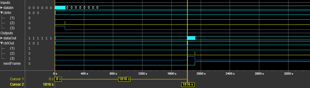
This figure shows a sample output and latency of the LDPC Decoder block for a scalar input when you use default settings for the block parameters. The latency of the block is 2796 clock cycles.

This figure shows a sample output and latency of the LDPC Decoder block for a 8-by-1 vector input when you use default settings for the block parameters. The latency of the block is 1816 clock cycles.
References
[1] Gallager, R. “Low-Density Parity-Check Codes.” IEEE Transactions on Information Theory 8, no. 1 (January 1962): 21–28. https://doi.org/10.1109/TIT.1962.1057683.
[2] Hocevar, D.E. “A Reduced Complexity Decoder Architecture via Layered Decoding of LDPC Codes.” In IEEE Workshop On Signal Processing Systems, 2004. SIPS 2004, 107–12. Austin, Texas, USA: IEEE, 2004. https://doi.org/10.1109/SIPS.2004.1363033.
[3] Chen, Jinghu, R.M. Tanner, C. Jones, and Yan Li. "Improved Min-Sum Decoding Algorithms for Irregular LDPC Codes." In Proceedings. International Symposium on Information Theory, 2005. ISIT 2005. https://doi: 10.1109/ISIT.2005.1523374.
Extended Capabilities
Version History
Introduced in R2023b